
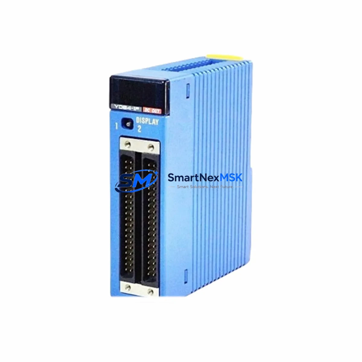
YOKOGAWA F3XD64-3F Retrofit-Ready Digital I/O for FA-M3 Control Systems
The YOKOGAWA F3XD64-3F is a 64-point digital I/O module engineered for seamless compatibility with the FA-M3 Series programmable controller platform. As legacy FA-M3 installations reach end-of-life or require capacity expansion, the F3XD64-3F serves as the primary retrofit solution — enabling engineers to modernize aging control cabinets without redesigning the entire automation architecture. Whether you are replacing a discontinued module, recovering from an unplanned failure, or executing a planned system upgrade, the F3XD64-3F delivers the electrical, mechanical, and software compatibility required to restore and extend production continuity.
This module slots directly into the FA-M3 base unit backplane, maintaining full compatibility with the F3SP series CPU modules, including the F3SP28-3N, F3SP38-6N, and F3SP59-7S. The 64-point I/O capacity is distributed across mixed digital input and output channels, making it suitable for high-density machine control, conveyor sequencing, valve actuation, and sensor interfacing in process and discrete manufacturing environments. Terminal wiring follows the standard FA-M3 connector layout, which means existing field cables can be reconnected without re-termination in most retrofit scenarios — a critical factor in minimizing downtime during planned maintenance windows.
When integrating the F3XD64-3F into an existing FA-M3 rack, engineers should verify the power supply capacity of the F3BU04-0N or F3BU16-0N base unit. Each additional I/O module draws current from the backplane bus, and high-density configurations with multiple F3XD64-3F modules may require supplemental power via the F3PU20-0S power supply module. Slot addressing is configured automatically by the CPU upon rack scan, but module position must be documented and cross-referenced against the existing ladder logic program to ensure I/O map consistency. Any change in slot assignment will require corresponding updates in the WIDE Field Network or WideField3 programming environment.
For installations that include communication modules such as the F3LC11-1F LONWORKS interface or the F3LE01-5T Ethernet module, the F3XD64-3F integrates without protocol conflict. The FA-M3 backplane arbitrates all module communication internally, so adding or replacing I/O modules does not disrupt active network sessions on the communication bus. This is particularly important in continuous process environments where the F3LC31-2N FL-net module or PROFIBUS-DP adapters are managing real-time data exchange with SCADA systems or distributed control nodes.
HMI compatibility is another key consideration during retrofit planning. If the existing system uses a YOKOGAWA UM33A or a third-party panel running Modbus TCP, the I/O tag database must be reviewed after module replacement. Screen objects mapped to specific I/O addresses will continue to function correctly provided the F3XD64-3F occupies the same rack slot as the replaced module. Where slot reassignment is unavoidable, HMI tag remapping should be completed and tested in simulation mode before live commissioning.
Field commissioning of the F3XD64-3F follows a structured sequence: power-down the rack, seat the module, reconnect field terminals, restore power, and perform a forced I/O test from the WideField3 online monitor. Each output channel should be individually energized and verified against the field device response. Input channels should be tested by actuating the connected sensors or switches and confirming the corresponding bit state in the CPU data register. This process typically requires two to four hours per rack depending on I/O density and field accessibility.
All F3XD64-3F modules supplied by SMARTNEXMSK are sourced from verified industrial channels, individually tested for electrical integrity prior to shipment, and covered by a 12-month warranty against manufacturing defects and functional failure. Inventory is maintained in stock for immediate dispatch, supporting both emergency replacement orders and scheduled retrofit projects. Fast global shipping is available to minimize the impact of unplanned downtime on production schedules.
Upgrade Compatibility Table
| Parameter | Detail |
|---|---|
| Compatible Platform | YOKOGAWA FA-M3 Series (R, e, V) |
| I/O Points | 64-point Digital Mixed I/O |
| Backplane Interface | FA-M3 Standard Backplane Bus (F3BU04-0N / F3BU16-0N) |
| Compatible CPUs | F3SP28-3N, F3SP38-6N, F3SP59-7S, F3SP67-6S |
| Terminal Wiring | Standard FA-M3 connector — existing field cables reusable |
| Communication Compatibility | FL-net (F3LC31-2N), Ethernet (F3LE01-5T), PROFIBUS-DP |
| Programming Environment | WideField3 / WIDE Field Network |
| Installation Requirement | Verify backplane power budget; update I/O map if slot changes |
| Retrofit Recommendation | Direct drop-in replacement; same slot position preferred |
| Commissioning Focus | Forced I/O test, HMI tag verification, communication link check |
| Warranty | 12 Months — covers manufacturing defects and functional failure |
Retrofit Planning for Existing Automation Systems
A successful FA-M3 retrofit begins with a complete audit of the existing rack configuration. Document every module position, including the F3XD64-3F slot, the CPU module type, any F3PU20-0S power supply modules, and all communication cards installed in the base unit. Cross-reference this layout against the WideField3 project file to confirm that I/O addresses, network node assignments, and inter-module references are accurately captured before any hardware is disturbed.
In multi-rack systems connected via the F3BU16-0N expansion base, each sub-rack must be individually audited. The F3XD64-3F modules in expansion racks are addressed sequentially from the master rack, and any change in module count or position will shift the address map for all downstream modules. Engineers should prepare a revised I/O allocation table and have it reviewed by the control system programmer before proceeding with physical installation.
Where the existing system includes analog I/O modules such as the F3AD08-6R or F3DA04-6R alongside digital modules, the retrofit plan must account for mixed-signal wiring segregation. Analog and digital commons should remain isolated on separate terminal blocks to prevent ground loop interference after the new F3XD64-3F is installed. If the control cabinet also houses a YOKOGAWA STARDOM FCN autonomous controller or a third-party DCS interface card, communication isolation between the FA-M3 backplane and the external network must be verified post-installation.
Programming cable access is required during commissioning. The F3XD64-3F does not require firmware flashing, but the WideField3 project must be downloaded to the CPU after any rack configuration change. Ensure the RS-232C or USB programming cable and the corresponding WideField3 license are available on-site before the maintenance window begins.
Downtime Control During System Migration
Minimizing production downtime during an FA-M3 module replacement requires preparation that begins well before the maintenance window. The existing ladder logic program should be uploaded from the CPU and archived as a baseline. A full rack configuration report should be exported from WideField3 and stored alongside the program backup. This ensures that if any issue arises during commissioning, the system can be restored to its pre-retrofit state within minutes.
Where production schedules permit only short maintenance windows, a pre-staged replacement strategy is recommended. The F3XD64-3F can be pre-configured and bench-tested against a spare FA-M3 base unit before the live system is touched. This approach reduces in-cabinet work time to the physical swap and terminal reconnection, typically achievable within 30 to 60 minutes for a single-module replacement.
For systems where continuous operation is critical, a parallel run strategy may be appropriate. A temporary FA-M3 sub-rack with the new F3XD64-3F can be connected in parallel with the existing rack, with I/O signals cross-wired and monitored simultaneously. Once the new module is confirmed operational, the cutover can be executed during a brief planned stop without the risk of extended unplanned downtime.
After cutover, the first 24 hours of operation should be monitored closely. Review the CPU diagnostic registers in WideField3 for any I/O error flags, check communication link status on all connected network modules, and confirm that HMI screens are displaying correct process values. Any discrepancy should be investigated immediately to prevent cascading faults in the control system.
Retrofit Support FAQ
Q: Is the F3XD64-3F a direct replacement for discontinued FA-M3 digital I/O modules?
A: Yes. The F3XD64-3F is electrically and mechanically compatible with the FA-M3 backplane and uses the same terminal connector layout as earlier-generation digital I/O modules in the FA-M3 family. In most cases, existing field wiring can be reconnected without modification. Verify the I/O point count and channel assignment against your existing program before installation.
Q: What commissioning steps are required after installing the F3XD64-3F?
A: After seating the module and reconnecting field terminals, restore rack power and perform a forced I/O test from the WideField3 online monitor. Verify each input and output channel individually. If the module occupies a different slot than the replaced unit, update the I/O address map in the program and re-download to the CPU before resuming automatic operation.
Q: How do I verify wiring compatibility before installation?
A: Compare the terminal block pinout of the F3XD64-3F against the original module’s wiring diagram. The FA-M3 standard connector layout is consistent across the digital I/O module family, but confirm signal polarity, common terminal grouping, and any sink/source wiring differences specific to your field devices before reconnecting cables.
Q: What does the 12-month warranty cover?
A: All F3XD64-3F modules supplied by SMARTNEXMSK carry a 12-month warranty covering manufacturing defects and functional failure under normal operating conditions. Warranty service includes replacement or repair at no additional cost. Modules damaged by incorrect installation, overvoltage, or environmental factors outside the specified operating range are not covered. Contact our technical team for warranty claims and return authorization.
© 2026 SMARTNEXMSK. All rights reserved.
Original Source: https://smartnexmsk.com
Contact: [email protected] | +86 18259474341



