
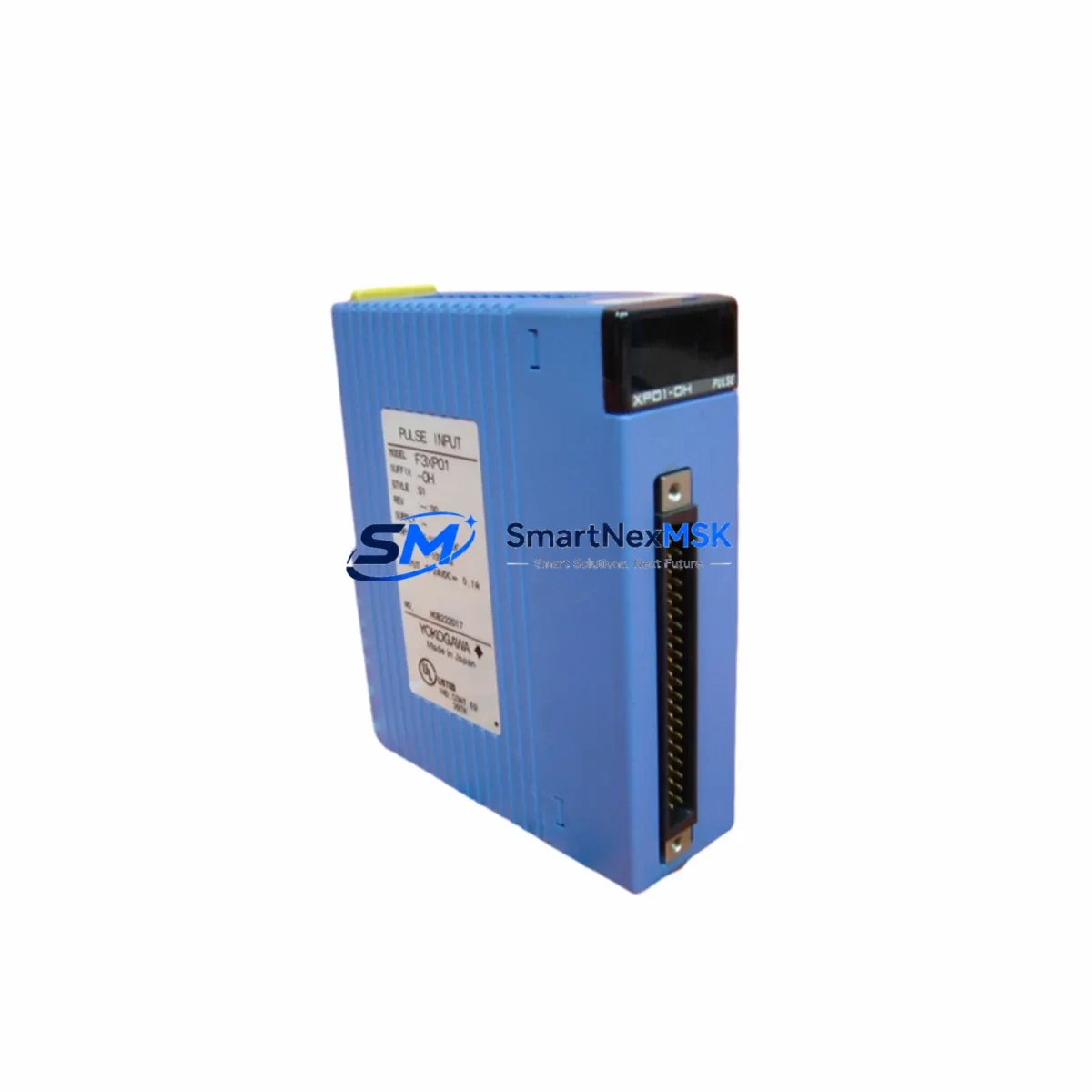
YOKOGAWA F3XP01-0H Spare for FA-M3 Automation: Spare Replacement & Industrial Downtime Risk Control
The YOKOGAWA F3XP01-0H is a 4-channel high-speed counter module designed for the FA-M3 programmable controller series. With a maximum counting frequency of 200 kHz per channel, this module is widely deployed in precision motion control, encoder feedback loops, flow metering, and high-throughput production line monitoring. When an F3XP01-0H fails or reaches end-of-service, unplanned downtime in encoder-driven or pulse-counting applications can cascade rapidly across the control system. Maintaining a verified original spare in your parts inventory is the most reliable strategy for fast recovery and sustained production continuity.
Each unit supplied by SMARTNEXMSK is sourced as an original YOKOGAWA component, individually tested prior to dispatch, and backed by a 12-month warranty. We support both emergency replacement orders and planned maintenance procurement, with stock available for immediate shipment.
Spare Maintenance Table
| Parameter | Specification / Detail |
|---|---|
| Part Number / SKU | F3XP01-0H |
| Brand | YOKOGAWA |
| Series | FA-M3 (STARDOM / Sequence CPU compatible) |
| Module Type | High-Speed Counter Module |
| Input Channels | 4 channels |
| Max Counting Frequency | 200 kHz per channel |
| Input Signal Type | Differential line driver / open collector pulse |
| Counter Mode | Up / Down / Up-Down (quadrature encoder support) |
| Power Supply | Supplied via FA-M3 backplane (5 VDC internal bus) |
| Mounting | FA-M3 base unit slot (standard module pitch) |
| Operating Temperature | 0 °C to 55 °C |
| Storage Temperature | -20 °C to 70 °C |
| Relative Humidity | 10% to 90% RH (non-condensing) |
| Origin | Japan |
| Compatibility | FA-M3 F3SP series CPU modules; direct slot replacement |
| Condition | Original, pre-shipment tested |
| Warranty | 12 months from date of shipment |
| Lead Time | In stock — ships within 1–3 business days |
Maintenance Planning for Continuous Operation
When scheduling replacement of the F3XP01-0H in a planned or corrective maintenance window, experienced maintenance engineers treat this module as part of a broader inspection of the FA-M3 control cabinet. The high-speed counter module interfaces directly with encoder wiring and pulse-generating field devices, so any replacement event is an opportunity to verify the integrity of adjacent components before returning the system to service.
Start by inspecting the FA-M3 base unit (F3BU-series backplane) for signs of oxidation on the module connector pins, which can cause intermittent counter read errors that are often misdiagnosed as module failure. Check the F3SP-series CPU module firmware version to confirm compatibility with the F3XP01-0H counter configuration parameters — mismatched firmware can cause initialization faults after module swap.
The F3PU20-0S or F3PU30-0S power supply module should be load-tested during the same maintenance window. A degraded power supply delivering marginal 5 VDC to the backplane is a common root cause of high-speed counter instability and spurious count errors. Replace or bench-test the power supply if output ripple exceeds specification.
Encoder signal wiring connected to the F3XP01-0H input terminals should be inspected for shield continuity and terminal torque. Loose connections on the F3-series terminal block assemblies or field wiring connectors are a frequent source of noise-induced miscounts in high-frequency applications. If the installation uses differential line driver encoders, verify that the signal isolator or line receiver upstream of the module input is functioning correctly — a failing isolator can corrupt the pulse train and cause the counter to report erratic values even when the module itself is healthy.
For cabinets running mixed I/O, also inspect the F3XD-series digital input modules and F3YD-series digital output modules in adjacent slots. Slot-to-slot crosstalk from high-frequency counter signals is rare but documented in dense FA-M3 configurations; proper slot assignment per YOKOGAWA’s module placement guidelines should be confirmed. If the system includes F3LC-series communication modules for MODBUS or Ethernet/IP data exchange, verify that counter data is being correctly mapped and that no address conflicts exist after the module replacement.
Where the FA-M3 system interfaces with an HMI — such as a YOKOGAWA UM33A or compatible panel display — confirm that counter channel tag addresses are correctly re-linked after the replacement module is initialized. HMI tag mapping errors following module swaps are a common source of post-maintenance alarms that delay return-to-service sign-off.
Finally, review the fuse and circuit protection for the encoder power supply circuit. A blown 24 VDC encoder supply fuse on the field terminal strip is sometimes the actual cause of a counter module appearing to malfunction, and replacing the module without checking the fuse will result in repeat failure. Stocking a set of replacement fuses alongside the F3XP01-0H spare is standard practice in well-managed FA-M3 maintenance programs.
Site Replacement Workflow
Step 1 — Isolation: Place the FA-M3 CPU in STOP mode via the mode selector or engineering software (YOKOGAWA ToolBox or WideField3). Confirm all counter channel outputs are in a safe state before proceeding.
Step 2 — Documentation: Record the current module slot position, wiring terminal assignments, and counter configuration parameters (preset values, latch settings, comparison outputs) from the CPU program or module configuration tool. Photograph the wiring before disconnection.
Step 3 — Module Removal: Disconnect field wiring from the F3XP01-0H terminal block. Release the module locking lever and extract the module from the FA-M3 base unit slot. Inspect the backplane connector for damage or contamination.
Step 4 — Replacement Installation: Insert the new F3XP01-0H into the same slot. Reconnect field wiring per the documented terminal assignments. Confirm terminal torque to specification.
Step 5 — Configuration Restore: Using WideField3 or ToolBox, download the counter module configuration to the new module. Verify preset values, count direction, and comparison output settings match the original configuration.
Step 6 — Functional Verification: Return the CPU to RUN mode. Apply a known pulse source to each counter channel and verify count accuracy. Confirm HMI tag values update correctly. Log the replacement in the maintenance record.
This workflow supports direct replacement of legacy F3XP01-0H units without requiring CPU program modification, preserving system compatibility and minimizing total downtime to under two hours in most field scenarios.
Spare Parts Support FAQ
Q1: Is the F3XP01-0H still in production, and how long can I source original spares?
The F3XP01-0H is a mature FA-M3 series module. SMARTNEXMSK maintains stock of original units to support long-term maintenance of installed FA-M3 systems. We recommend customers with critical FA-M3 installations secure at least one spare unit per cabinet to protect against lead-time risk as the module approaches end-of-availability. Contact us for volume pricing on multi-unit spare stock orders.
Q2: How is each unit tested before shipment?
Every F3XP01-0H is powered up and functionally tested on an FA-M3 base unit prior to dispatch. Counter channel input response, output signal integrity, and backplane communication are verified. A test report is available upon request. Units are packed in anti-static packaging with physical protection for international shipment.
Q3: Can the F3XP01-0H replace other FA-M3 counter module variants?
The F3XP01-0H is a specific 4-channel 200 kHz variant within the FA-M3 counter module family. Compatibility with adjacent variants (such as the F3XP04-0H or F3XP08-0H if applicable) depends on channel count requirements and CPU program configuration. We recommend confirming the exact part number against your system’s I/O list before ordering. Our technical team can assist with compatibility verification.
Q4: What does the 12-month warranty cover?
The 12-month warranty covers manufacturing defects and functional failure under normal operating conditions within the FA-M3 system environment. It does not cover damage resulting from incorrect installation, overvoltage, or use outside the module’s rated environmental specifications. Warranty claims are processed with return of the defective unit; replacement or refund is issued within the agreed lead time.
© 2026 SMARTNEXMSK. All rights reserved.
Original Source: https://smartnexmsk.com
Contact: [email protected] | +86 18259474341



