
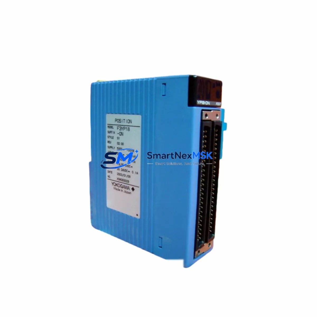
YOKOGAWA F3YD32-1A Retrofit-Ready Digital Output Module for FA-M3 Control Systems
The YOKOGAWA F3YD32-1A is a 32-point transistor digital output module designed for the YOKOGAWA FA-M3 modular PLC platform. As legacy FA-M3 installations age and original spare parts become increasingly difficult to source, the F3YD32-1A has become a critical retrofit component for engineers managing aging control cabinets, upgrading discontinued I/O racks, and maintaining production continuity without full system replacement.
This module delivers NPN transistor sink output across 32 channels, with a rated load voltage of 12–24 VDC and a maximum load current of 0.1 A per point. Its compact form factor and direct backplane compatibility with the FA-M3 F3SP-series CPU racks make it a drop-in replacement for failed or end-of-life output modules in existing control panels. Whether you are restoring a stopped production line, expanding I/O capacity in a running system, or migrating from an older F3YD16-series module, the F3YD32-1A integrates without requiring changes to the existing ladder logic or HMI screen configurations.
Upgrade Compatibility Table
| Parameter | F3YD32-1A Specification | Retrofit Notes |
|---|---|---|
| Output Points | 32 points (NPN transistor) | Replaces 16-pt modules with address remapping required |
| Load Voltage | 12–24 VDC | Verify field device voltage before wiring |
| Max Load Current | 0.1 A per point / 1.6 A per common | Check power supply capacity on F3BU-series base unit |
| Backplane Interface | FA-M3 standard bus connector | Compatible with F3BU04-0N, F3BU08-0N, F3BU16-0N racks |
| Module Slot Address | Configurable via CPU slot assignment | Confirm slot number in F3SP-series CPU I/O map before insertion |
| Communication Protocol | Internal FA-M3 backplane bus | No external protocol change; compatible with existing F3LC11-1N or F3LE01-5T Ethernet links |
| Replacement Path | F3YD16-1A → F3YD32-1A | Address offset adjustment needed in CPU program |
| Commissioning | Force output test via ToolBox FA software | Verify each channel with field device before going live |
| Warranty | 12-Month Warranty — covers manufacturing defects and functional failure under normal operating conditions | |
Retrofit Planning for Existing Automation Systems
Successful integration of the F3YD32-1A into a running FA-M3 system requires a structured pre-installation review. Begin by auditing the existing F3BU-series base unit to confirm available slot positions and total power budget. The F3PU10-0S or F3PU20-0S power supply modules feeding the rack must have sufficient remaining capacity to support the additional 32-channel output load — particularly if the retrofit is expanding I/O rather than replacing a failed module on a one-for-one basis.
Terminal wiring is the most time-sensitive step. The F3YD32-1A uses a 40-pin MIL connector interface. If the existing cabinet was wired for an older F3YD16-1A or a relay output module such as the F3YR16-0N, the field wiring harness will need to be re-terminated or adapted. Prepare a channel-by-channel wiring map before the maintenance window opens to minimize downtime.
For systems using the F3LC11-1N or F3LE01-5T communication modules for SCADA or DCS integration, no changes to the communication link are required. The F3YD32-1A operates entirely on the internal FA-M3 backplane bus and is transparent to upstream Modbus TCP or MELSEC protocol traffic. However, if the HMI — such as a YOKOGAWA ProSafe-RS operator station or a third-party panel running ToolBox FA — has hardcoded I/O addresses, those screen tags must be reviewed and updated to reflect the new module’s slot assignment and point count.
Where the retrofit involves migrating from a 16-point to a 32-point output module, the CPU program stored in the F3SP-series controller must be updated to reflect the expanded I/O map. Use YOKOGAWA ToolBox FA to perform an offline simulation before downloading the revised program to the live CPU. Back up the existing program to a CF card or PC before any modification. If the system includes an F3EM-series memory expansion module, verify that the program storage capacity is sufficient for the updated logic.
Downtime Control During System Migration
Minimizing production downtime during a module swap requires preparation that begins well before the scheduled maintenance window. The recommended approach is to pre-configure the replacement F3YD32-1A offline — verifying LED indicator behavior, performing a bench-level force output test using ToolBox FA, and confirming that the module powers up correctly when inserted into a spare F3BU-series rack.
During the live swap, follow a structured sequence: isolate the affected rack section, remove the failed or end-of-life module, insert the F3YD32-1A, restore power, and confirm that the CPU recognizes the new module without generating a hardware fault alarm. If the F3SP-series CPU enters a STOP state upon module insertion, check the I/O configuration file and re-download the updated program. For systems with redundant CPU configurations using F3SP71-4S or F3SP76-7S modules, the standby CPU can maintain output control while the active side is updated, reducing the effective downtime to near zero.
After the module is online, perform a channel-by-channel output verification against the field device list. Confirm that actuators, solenoid valves, motor starters, and signal lamps respond correctly to forced output commands before releasing the system to automatic control. Document the commissioning results and update the as-built wiring diagram and I/O list to reflect the new module configuration.
Retrofit Support FAQ
Q1: Is the F3YD32-1A a direct replacement for the F3YD16-1A?
The F3YD32-1A is functionally compatible with FA-M3 racks that previously housed the F3YD16-1A, but it doubles the output point count. The physical slot footprint is identical, and the backplane connector is the same. However, the CPU I/O address map must be updated to account for the additional 16 output points. If the existing program only uses 16 outputs, the upper 16 channels of the F3YD32-1A will remain unused but will not cause any fault condition.
Q2: What commissioning steps are required after installation?
After physical installation, use YOKOGAWA ToolBox FA to perform an I/O force test on each of the 32 output channels. Confirm that the corresponding field devices respond correctly. Check the CPU diagnostic screen for any module error codes. If the system uses an F3LE01-5T Ethernet communication module for remote monitoring, verify that the SCADA tag database reflects the updated I/O addresses before returning the system to automatic operation.
Q3: How do I verify wiring compatibility before installation?
Compare the terminal connector type and pin assignment of the F3YD32-1A against the existing field wiring harness. The module uses a 40-pin MIL-spec connector. If the existing harness was built for a 20-pin connector (as used on some F3YD16-series modules), a transition cable or re-termination will be required. Confirm load voltage and current ratings for each connected field device against the module’s 0.1 A per point and 1.6 A per common specifications.
Q4: What does the 12-month warranty cover?
All F3YD32-1A units supplied by SMARTNEXMSK carry a 12-month warranty from the date of shipment. The warranty covers manufacturing defects and functional failure under normal operating conditions, including backplane communication faults, output transistor failure, and LED indicator malfunction. Units damaged by incorrect wiring, overvoltage, or physical impact are not covered. Each unit undergoes pre-shipment functional testing before dispatch.
© 2026 SMARTNEXMSK. All rights reserved.
Original Source: https://smartnexmsk.com
Contact: [email protected] | +86 18259474341



