
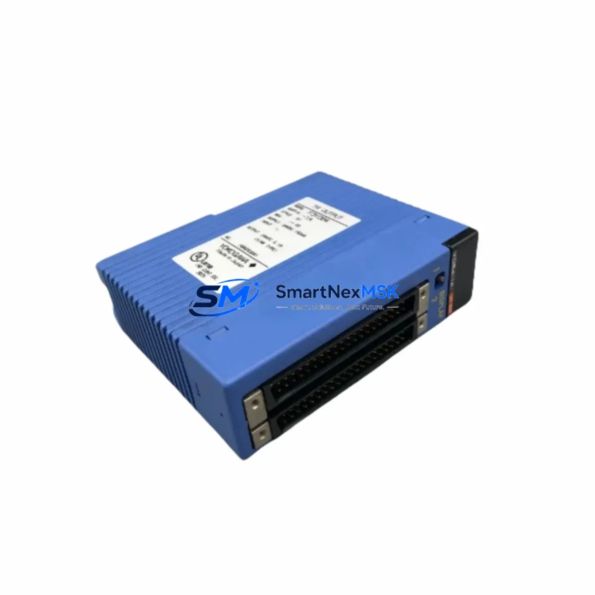
YOKOGAWA F3YD64-1A Maintenance-Ready Spare for FA-M3 Automation
The YOKOGAWA F3YD64-1A is a 64-point NPN open-collector transistor digital output module designed for the YOKOGAWA FA-M3 modular PLC platform. In industrial environments where continuous operation is non-negotiable, maintaining a verified spare of the F3YD64-1A in your parts inventory is a frontline strategy against unplanned downtime. Whether you are managing a process line, a packaging system, or a discrete manufacturing cell, this module serves as the critical interface between your FA-M3 controller and field actuators — solenoid valves, motor starters, indicator lamps, and relay coils.
Sourced as an original YOKOGAWA component, each F3YD64-1A unit shipped by SMARTNEXMSK undergoes pre-shipment functional verification to confirm output channel integrity, terminal continuity, and module identification. Our 12-month warranty covers manufacturing defects and ensures your maintenance team receives a field-ready replacement, not a shelf-aged unknown.
Spare Maintenance Table
| SKU / Part Number | F3YD64-1A |
| Brand | YOKOGAWA |
| Compatible Platform | YOKOGAWA FA-M3 Modular PLC |
| Module Type | Digital Output Module — NPN Transistor (Open Collector) |
| Output Points | 64 points |
| Output Voltage Range | 5–24 VDC |
| Max Load Current per Point | 0.1 A |
| Isolation Method | Photocoupler isolation |
| Connector Type | 40-pin MIL connector (×2) |
| Backplane Compatibility | FA-M3 base units (F3BU04-0N, F3BU08-0N, F3BU16-0N series) |
| Operating Temperature | 0 °C to 55 °C |
| Storage Temperature | −20 °C to 75 °C |
| Humidity | 10–90% RH (non-condensing) |
| Origin | Japan |
| Pre-shipment Test | Output channel continuity and module ID verified |
| Warranty | 12 Months — Manufacturing Defects Covered |
| Lead Time | In-stock units ship within 2 business days |
Maintenance Planning for Continuous Operation
When a maintenance or procurement engineer schedules a replacement of the F3YD64-1A, the replacement event should not be treated in isolation. The FA-M3 control cabinet housing this module typically contains a range of interdependent components, and a thorough inspection during the same maintenance window significantly reduces the risk of a secondary failure shortly after restart.
Begin with the FA-M3 CPU module (such as the F3SP28-3N or F3SP38-6N) — confirm firmware version compatibility with the replacement output module and verify that the CPU scan cycle is within normal range. Next, inspect the FA-M3 power supply module (F3PU20-0S or equivalent) for output voltage stability; a degraded power supply is a common root cause of intermittent output module faults that are misdiagnosed as module failure.
Check the digital input modules in the same rack — particularly the F3XD32-3H or F3XD64-3H — for signs of contact wear or signal noise that may have contributed to abnormal output switching cycles. If the cabinet includes analog I/O modules such as the F3AD04-1N or F3DA04-1N, verify signal scaling and loop integrity, as analog feedback loops often interact with digital output sequences in process control applications.
Inspect all terminal blocks and wiring harnesses connected to the 40-pin MIL connectors of the F3YD64-1A. Loose or corroded terminals are a leading cause of intermittent output faults. If the system uses relay output expansion modules or external relay panels driven by the transistor outputs, check coil resistance and contact condition on each relay. For systems with communication modules such as the F3LC11-1F (MELSEC-compatible link) or F3LE01-5T (Ethernet), confirm that the network topology and I/O refresh timing remain unaffected after the module swap.
Where signal isolators are installed between the FA-M3 output channels and field devices, verify isolator output voltage levels and response time. Finally, review the fuse and circuit protection on each output group — a blown fuse on the load side is frequently overlooked and will cause the replacement module to appear faulty during commissioning.
Site Replacement Workflow
Replacing the F3YD64-1A on-site follows a structured sequence to minimize downtime and avoid configuration errors:
1. Pre-replacement verification: Confirm the replacement unit’s part number label matches F3YD64-1A exactly. Check the module revision if your FA-M3 system uses a specific firmware baseline. Document the current I/O mapping and output status before powering down.
2. Safe power-down: Follow your site’s lockout/tagout (LOTO) procedure. Power down the FA-M3 base unit from the power supply module before removing the output module. Do not hot-swap unless your FA-M3 configuration explicitly supports it.
3. Module removal and installation: Disconnect the 40-pin MIL connectors carefully — do not force or bend connector pins. Seat the replacement F3YD64-1A firmly into the backplane slot. Reconnect field wiring connectors and verify terminal seating.
4. Power-up and diagnostics: Restore power and observe the module’s LED status indicators. The FA-M3 CPU should recognize the module automatically. Run a forced output test from the engineering workstation to confirm all 64 output channels respond correctly before returning the system to automatic mode.
5. Documentation: Record the replacement date, module serial number, and test results in your maintenance log. Update your spare parts inventory to reorder a replacement F3YD64-1A for the next maintenance cycle.
This workflow applies equally to planned preventive maintenance replacements and emergency corrective actions, ensuring system compatibility is maintained and downtime is kept to a minimum.
Spare Parts Support FAQ
Q1: Is the F3YD64-1A you supply an original YOKOGAWA component?
Yes. All F3YD64-1A units supplied by SMARTNEXMSK are sourced as original YOKOGAWA components. Each unit is pre-shipment tested for output channel continuity and module identification before dispatch. A 12-month warranty against manufacturing defects is included with every shipment.
Q2: How do I verify compatibility with my existing FA-M3 system before ordering?
The F3YD64-1A is compatible with all standard FA-M3 base units including the F3BU04-0N, F3BU08-0N, and F3BU16-0N series. If your system uses a non-standard backplane or a legacy FA-M3 configuration, please contact our technical team at [email protected] with your base unit model and CPU firmware version for confirmation before ordering.
Q3: What is your recommended spare parts stocking strategy for the F3YD64-1A?
For production-critical systems, we recommend maintaining a minimum of one F3YD64-1A per FA-M3 rack in your on-site spare parts inventory. For multi-line facilities, a centralized buffer stock of 2–3 units is advisable given the module’s role as a high-density output interface. Long-term supply continuity is supported through our standing order program.
Q4: What happens if the replacement module shows a fault LED after installation?
A fault LED after installation most commonly indicates a wiring issue on the field connector, a blown load-side fuse, or a CPU configuration mismatch — not a module defect. Follow the site replacement workflow above to isolate the cause. If the fault persists after verifying wiring, fuses, and CPU recognition, contact SMARTNEXMSK support. Units confirmed defective within the 12-month warranty period will be replaced at no charge.
© 2026 SMARTNEXMSK. All rights reserved.
Original Source: https://smartnexmsk.com
Contact: [email protected] | +86 18259474341



