
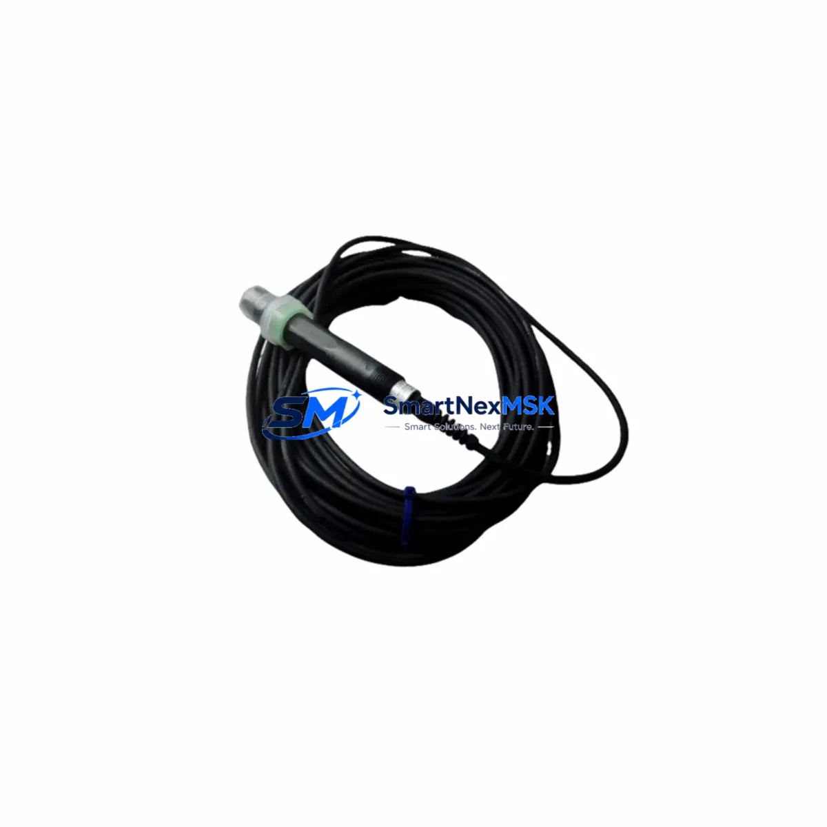
Yokogawa FU20-20-T1-NPT Maintenance-Ready Spare for FU20 Automation
The Yokogawa FU20-20-T1-NPT is a clamp-on ultrasonic flow sensor from the FU20 Wide Body Series, engineered for non-invasive flow measurement in industrial process environments. As a maintenance-ready original spare, this unit is stocked and tested to support rapid replacement in continuous-process plants, utilities, and manufacturing facilities where unplanned downtime carries significant operational cost. Whether you are executing a planned shutdown, responding to a sensor fault, or building a critical spare inventory for aging YOKOGAWA flow measurement systems, the FU20-20-T1-NPT delivers verified compatibility and reliable performance from day one.
Maintenance engineers and procurement teams working with YOKOGAWA flow instrumentation recognize the FU20 series as a field-proven platform. The NPT threaded connection variant (FU20-20-T1-NPT) is widely deployed on pipe sizes in the DN50–DN300 range, paired with YOKOGAWA ADMAG or ROTAMASS transmitters and integrated into DCS or PLC-based flow control loops. When this sensor reaches end-of-life or exhibits signal drift, the replacement window is narrow — process continuity depends on having a verified spare on hand or a supplier capable of same-week dispatch.
This listing provides an original YOKOGAWA FU20-20-T1-NPT sensor, pre-shipment tested, with a 12-month warranty covering manufacturing defects and functional performance. Each unit ships with full documentation support to facilitate site acceptance and commissioning records.
Spare Maintenance Table
| Parameter | Specification / Value |
|---|---|
| Part Number / SKU | FU20-20-T1-NPT |
| Brand | YOKOGAWA |
| Series | FU20 Wide Body Ultrasonic Flow Sensor |
| Sensor Type | Clamp-on Ultrasonic (Transit-Time) |
| Connection Type | NPT Threaded |
| Applicable Pipe Size | DN50 – DN300 (nominal, application-dependent) |
| Fluid Compatibility | Liquids (water, chemicals, hydrocarbons — per process spec) |
| Output Signal | Analog / Pulse (paired with compatible YOKOGAWA transmitter) |
| Installation Method | Non-invasive clamp-on, no pipe cutting required |
| Operating Temperature | -40°C to +150°C (sensor body, application-dependent) |
| Protection Rating | IP67 (dust-tight, water-immersion rated) |
| Country of Origin | Japan |
| Compatibility | YOKOGAWA FU20 Series transmitters; DCS/PLC analog input modules |
| Maintenance Recommendation | Inspect coupling gel, cable integrity, and clamp torque every 12 months |
| Warranty | 12 Months — manufacturing defects and functional performance |
| Pre-Shipment Test | Yes — functional verification before dispatch |
| Lead Time | In stock — typically ships within 3–5 business days |
Maintenance Planning for Continuous Operation
Replacing the FU20-20-T1-NPT sensor in the field is rarely an isolated task. A thorough maintenance plan for the associated flow measurement loop should address the full signal chain to prevent repeat failures and ensure measurement accuracy is restored completely. Maintenance engineers should inspect and, where necessary, replace the following components during the same maintenance window:
The YOKOGAWA FU20 transmitter unit paired with this sensor should be checked for firmware version compatibility and calibration status — a sensor replacement without transmitter re-zeroing will introduce offset errors. The sensor coaxial cable assembly (typically a shielded, low-capacitance cable specific to the FU20 series) is a common wear item; inspect for jacket cracking, connector corrosion, and continuity. The coupling compound or acoustic gel pad between the sensor and pipe wall must be renewed at every sensor replacement to ensure ultrasonic signal transmission integrity.
At the control cabinet level, verify the 24VDC power supply module feeding the transmitter — voltage sag or ripple can cause erratic flow readings that mimic sensor failure. Check the analog input card on the DCS or PLC (4–20 mA channel) for correct scaling, input impedance, and channel isolation. If the flow signal feeds a safety instrumented system (SIS) or interlock relay, confirm that the relay coil voltage and contact ratings remain within specification after the sensor swap.
For installations where the FU20-20-T1-NPT feeds a YOKOGAWA CENTUM VP or ProSafe-RS system, review the I/O module assignment and tag configuration in the engineering station before returning the loop to service. In older installations, the terminal strip and field junction box should be inspected for loose terminations, moisture ingress, and corrosion — these are frequent root causes of intermittent flow signal faults that are incorrectly attributed to sensor failure. Where signal isolators or loop-powered barriers are installed between the transmitter and the DCS input card, verify that the isolator output range and accuracy are still within calibration.
Finally, if the plant operates a YOKOGAWA FieldMate or PRM (Plant Resource Manager) asset management system, update the maintenance record for the FU20-20-T1-NPT tag, log the replacement date, and schedule the next planned inspection interval. Proactive spare parts inventory — keeping at least one FU20-20-T1-NPT and one spare cable assembly on the shelf — is the most cost-effective strategy for minimizing flow measurement downtime in critical process lines.
Site Replacement Workflow
The FU20-20-T1-NPT is designed for field replacement without pipe modification, making it one of the more maintainable sensor types in the YOKOGAWA flow product line. The following workflow is recommended for site engineers executing a planned or emergency replacement:
Step 1 — Isolation and Safety: Place the flow control loop in manual mode at the DCS or PLC. Isolate the transmitter power supply and confirm zero energy state at the field junction box. Document the existing sensor position, clamp alignment marks, and cable routing before disassembly.
Step 2 — Sensor Removal: Release the clamp assembly and carefully remove the FU20-20-T1-NPT sensor from the pipe. Clean the pipe surface and remove residual coupling compound. Inspect the pipe wall for corrosion, pitting, or coating damage that could affect acoustic coupling on the new sensor.
Step 3 — New Sensor Installation: Apply fresh acoustic coupling compound to the sensor face. Position the FU20-20-T1-NPT at the same axial location as the original unit, observing the upstream/downstream orientation markings. Torque the clamp to the manufacturer’s specification. Reconnect the coaxial cable, ensuring the connector is fully seated and the cable is routed away from high-voltage conductors.
Step 4 — Commissioning and Verification: Restore transmitter power and allow the unit to complete its self-diagnostic cycle. Verify the 4–20 mA output at the DCS analog input card against a known reference flow condition or a portable clamp-on check meter. Re-zero the transmitter if required. Return the loop to automatic control and confirm stable, noise-free flow indication.
This non-invasive replacement approach eliminates the need for process shutdown, pipe draining, or hot-work permits in most installations, significantly reducing the total downtime window compared to invasive flow meter types. Compatibility with the existing YOKOGAWA FU20 transmitter is maintained without re-parameterization in standard like-for-like replacements.
Spare Parts Support FAQ
Q1: Is the FU20-20-T1-NPT a direct drop-in replacement for older FU20 series sensors?
Yes, in standard like-for-like applications. The FU20-20-T1-NPT maintains mechanical and electrical compatibility with the FU20 Wide Body transmitter platform. If the original installation used a different cable length or coupling method, confirm the accessory part numbers before ordering. We recommend providing the original sensor nameplate data or transmitter model number when placing your order so our technical team can confirm compatibility.
Q2: What pre-shipment testing is performed on each unit?
Every FU20-20-T1-NPT unit undergoes functional verification prior to dispatch, including electrical continuity, insulation resistance, and acoustic transducer output checks. Units that do not meet YOKOGAWA OEM performance specifications are not shipped. A test record is available upon request for quality documentation purposes.
Q3: How should I manage spare parts inventory for FU20 series sensors in a multi-unit plant?
For plants operating three or more FU20-based flow measurement points, we recommend maintaining a minimum of one FU20-20-T1-NPT sensor and one spare cable assembly in the site stores. For critical process lines (e.g., custody transfer, reactor feed, or safety-critical flow interlocks), a two-unit buffer is advisable. Our team can support blanket order arrangements and scheduled replenishment to align with your annual maintenance budget cycle.
Q4: What does the 12-month warranty cover, and what is the claims process?
The 12-month warranty covers manufacturing defects and functional performance failures under normal operating conditions consistent with the YOKOGAWA FU20 series specification. Physical damage from incorrect installation, overpressure, or chemical incompatibility is excluded. To initiate a warranty claim, contact our sales team with the order reference, installation date, and a description of the fault. We will arrange return logistics and provide a replacement unit or repair at no additional cost within the warranty period.
© 2026 SMARTNEXMSK. All rights reserved.
Original Source: https://smartnexmsk.com
Contact: [email protected] | +86 18259474341



