
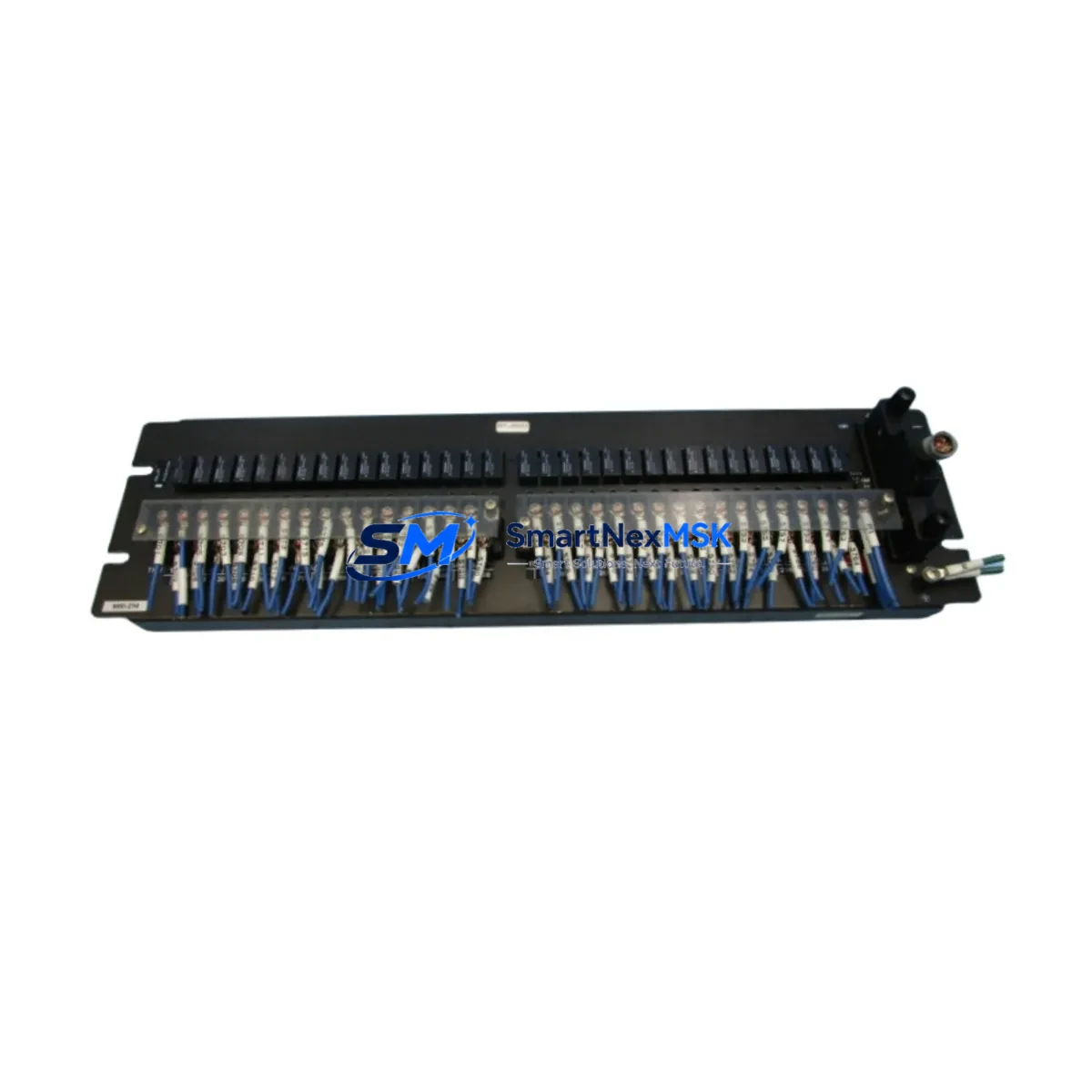
Yokogawa MRI-214*A Retrofit-Ready Relay Input Module: Compatible Modernization and Legacy System Upgrade
The Yokogawa MRI-214*A is a relay input board designed for use within the CENTUM VP and CS 3000 Distributed Control System (DCS) platforms — two of the most widely deployed process automation architectures in the petrochemical, power generation, and continuous manufacturing industries. As original MRI-214*A units reach end-of-life or become increasingly difficult to source through standard channels, plant engineers and maintenance teams are turning to verified retrofit-ready replacements to sustain system uptime without committing to a full platform migration.
This module serves as a direct functional replacement for the original Yokogawa MRI-214*A relay input board. It is engineered to slot into existing CENTUM VP and CS 3000 field control station (FCS) racks without requiring changes to the backplane wiring, I/O address mapping, or control logic. For facilities operating aging DCS infrastructure, this replacement path offers a cost-effective alternative to full system decommissioning while preserving the integrity of validated process control programs.
Upgrade Compatibility Table
| Parameter | Detail |
|---|---|
| SKU / Part Number | MRI-214*A |
| Brand | Yokogawa Electric Corporation |
| Compatible DCS Platform | CENTUM VP, CENTUM CS 3000 |
| Module Function | Relay Contact Input (Digital Input) |
| Backplane Interface | Compatible with standard CENTUM VP / CS 3000 FCS node racks |
| Installation Type | Direct card replacement — no rack modification required |
| Terminal Wiring | Retains original field terminal block layout; no rewiring required |
| I/O Address Mapping | Preserved from original module slot assignment |
| Communication Compatibility | Vnet/IP, V-net (legacy), compatible with existing FCS communication links |
| Replacement Recommendation | Direct swap for discontinued MRI-214*A; verify firmware revision before installation |
| Commissioning Notes | Confirm channel scan cycle, relay contact rating, and FCS builder configuration |
| Warranty | 12 Months from date of shipment |
| Origin | Japan |
| Shipping | Global express shipping available; ESD-safe packaging |
Retrofit Planning for Existing Automation Systems
Successful integration of the MRI-214*A replacement into a live CENTUM VP or CS 3000 system requires a structured pre-installation review. Before the module is swapped, the engineering team should audit the existing FCS node configuration using Yokogawa’s System View or FCS Builder tools to confirm the slot address, I/O channel assignments, and relay contact input parameters currently defined for the outgoing card.
Power supply capacity is a critical checkpoint. The CENTUM VP FCS node draws power from dedicated power supply modules — typically the PW481 or PW482 series — and the total load budget must be recalculated when introducing any replacement I/O card. If the existing power supply is already operating near its rated output, a parallel power supply module may need to be added to the node before the MRI-214*A is installed.
Field terminal connections are routed through terminal assembly units (TAU) or marshalling cabinets. The MRI-214*A uses a standard relay contact input terminal arrangement, and the field wiring from the existing TAU should be verified against the replacement module’s terminal block pinout before energizing. In most CENTUM VP installations, the terminal block is part of the node unit rather than the I/O card itself, which simplifies the card swap process significantly.
For systems running on the legacy CS 3000 platform, the communication backbone typically uses V-net — a proprietary Yokogawa token-ring network. When upgrading to CENTUM VP, the communication infrastructure may need to be migrated to Vnet/IP, which operates over standard Ethernet. In this scenario, the MRI-214*A replacement can be installed in the new CENTUM VP FCS node while the V-net to Vnet/IP migration is handled at the controller and network switch level. The ESB10D or ESB10S bus interface modules are commonly involved in this transition, and their compatibility with the new FCS node should be confirmed during the engineering review phase.
HMI screens built in Yokogawa’s CENTUM VP HIS (Human Interface Station) or the legacy CS 3000 Operator Station reference I/O tags by their FCS address. After the MRI-214*A is replaced, the HMI tag database should be validated to confirm that all relay input channels are correctly mapped and that alarm setpoints, interlock logic, and trend displays are functioning as expected. If the facility is also upgrading from the CS 3000 HIS to a CENTUM VP HIS, the tag migration should be completed and tested in a simulation environment before the live cutover.
Other components commonly involved in the same retrofit scope include the ALR111 alarm module, the ADV151 analog input card for process variable monitoring, the AAI141 analog input module for 4–20 mA field instruments, the DCV64 digital communication module for serial device integration, and the ACF11 field communication module for FOUNDATION Fieldbus segments. In control cabinets where space is limited, the RIO (Remote I/O) node units and their associated communication cables should also be inspected for wear and connector integrity before the retrofit is finalized.
Programming cable compatibility is another consideration for teams performing on-site configuration. The Yokogawa SCP440 or equivalent programming interface is used to connect a laptop running FCS Builder to the controller node for parameter verification and download. Confirm that the programming cable and software version are compatible with the target FCS firmware before the maintenance window begins.
Downtime Control During System Migration
Minimizing unplanned downtime is the primary operational constraint in any DCS relay input module replacement. The recommended approach is to perform the MRI-214*A swap during a scheduled maintenance window, with the affected FCS node placed in manual control mode prior to card removal. This ensures that the process remains under operator supervision through the HIS while the I/O card is physically replaced.
Before removing the original MRI-214*A, the control engineer should export the current FCS configuration from FCS Builder and save a timestamped backup. This backup preserves the full I/O parameter set, including relay contact input scan cycles, channel enable/disable states, and interlock assignments. If the replacement module requires a firmware update or parameter download, the backup file serves as the reference for restoring the exact pre-maintenance configuration.
For systems where the relay input channels feed into safety interlock logic or emergency shutdown sequences, a bypass procedure should be implemented in coordination with the process safety team before the card is removed. The bypass should be documented, time-limited, and reversed immediately after the replacement module is confirmed operational.
Once the MRI-214*A replacement is installed and the FCS node is returned to automatic control, a channel-by-channel functional test should be performed to verify that each relay contact input is reading correctly. This test involves actuating each field device connected to the module — such as limit switches, pressure switches, or relay contacts from motor control centers — and confirming that the corresponding I/O channel in the FCS reflects the correct state. The entire functional test sequence can typically be completed within two to four hours for a standard 16-channel relay input module, keeping total planned downtime well within a single shift.
Retrofit Support FAQ
Q1: Is the MRI-214*A replacement a direct drop-in for the original Yokogawa module?
Yes. The replacement MRI-214*A is designed to match the original module’s form factor, backplane connector, and terminal block layout. No rack modification or field rewiring is required for a standard card swap in a CENTUM VP or CS 3000 FCS node. However, we recommend verifying the firmware revision and FCS Builder parameter set before installation to ensure full compatibility with your specific system configuration.
Q2: What commissioning steps are required after installing the replacement module?
After physical installation, the FCS node should be powered up and the I/O channel status verified in System View. Each relay contact input channel should be tested by actuating the corresponding field device and confirming the correct state is displayed in the HIS. Alarm setpoints, interlock assignments, and trend tags should also be validated against the pre-maintenance FCS configuration backup.
Q3: Can this module be used in both CENTUM VP and CS 3000 systems?
The MRI-214*A is compatible with both CENTUM VP and CS 3000 FCS node architectures. For CS 3000 installations, confirm the node unit type and backplane revision. For CENTUM VP installations, confirm the FCS generation (R5 or later) and Vnet/IP network configuration. If you are migrating from CS 3000 to CENTUM VP as part of the same project, contact our technical team for a system-level compatibility review.
Q4: What does the 12-month warranty cover?
All MRI-214*A replacement modules supplied by SMARTNEXMSK carry a 12-month warranty from the date of shipment. The warranty covers manufacturing defects and functional failures under normal operating conditions. Each unit undergoes pre-shipment functional testing before dispatch. Warranty claims are supported by our technical team, and replacement units are dispatched within 5 business days of a confirmed warranty fault.
© 2026 SMARTNEXMSK. All rights reserved.
Original Source: https://smartnexmsk.com
Contact: [email protected] | +86 18259474341



