
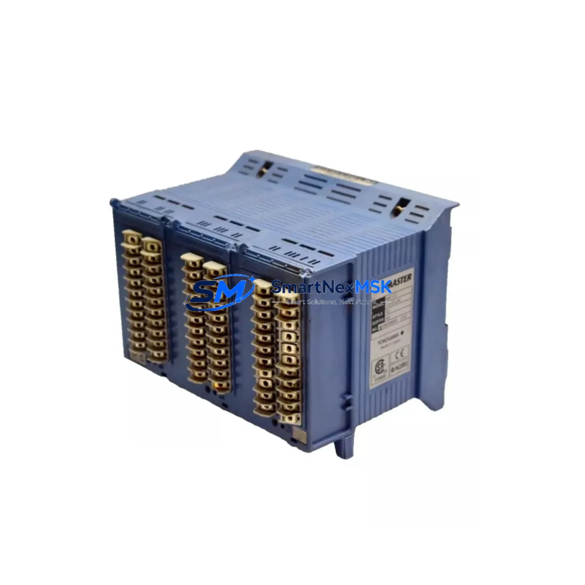
YOKOGAWA MX110-VTD-L30 Spare for MX100 Automation: Spare Replacement & Industrial Downtime Risk Control
The YOKOGAWA MX110-VTD-L30 is a 30-channel thermocouple and millivolt (mV) input module designed for the MX100 ScopeCorder data acquisition system. In industrial environments where continuous temperature monitoring is critical — from furnace control and heat treatment lines to energy management and process validation — an unplanned failure of this module can halt production and compromise data integrity. Sourcing a verified, maintenance-ready spare is the most effective strategy to minimize downtime and restore system operation quickly.
This listing provides an original YOKOGAWA MX110-VTD-L30 spare module, tested prior to shipment, backed by a 12-month warranty, and ready for immediate deployment into MX100 ScopeCorder systems. Whether you are a maintenance engineer managing a planned overhaul or a procurement engineer building a critical spare inventory, this module is stocked and available for fast dispatch.
Spare Maintenance Table
| Parameter | Specification |
|---|---|
| Part Number / SKU | MX110-VTD-L30 |
| Brand | YOKOGAWA |
| Series | MX100 ScopeCorder |
| Module Type | Thermocouple / mV Input Module |
| Number of Channels | 30 Channels |
| Input Types Supported | Thermocouple (K, J, T, E, R, S, B, N, W), mV |
| Measurement Range (mV) | ±100 mV (typical) |
| Isolation | Channel-to-channel isolated |
| Compatibility | YOKOGAWA MX100 ScopeCorder mainframe |
| Installation | Plug-in module, hot-swap capable (refer to MX100 manual) |
| Operating Temperature | 0°C to 50°C |
| Storage Temperature | -20°C to 60°C |
| Origin | Japan |
| Warranty | 12 Months |
| Pre-shipment Testing | Yes — functional verification before dispatch |
| Typical Application | Furnace monitoring, heat treatment, energy auditing, process validation |
| Maintenance Recommendation | Inspect terminal blocks and thermocouple wiring annually; verify cold junction compensation accuracy |
Maintenance Planning for Continuous Operation
When replacing the MX110-VTD-L30 in a live MX100 ScopeCorder system, a thorough site inspection is essential to prevent repeat failures and ensure measurement accuracy is fully restored. Maintenance engineers should treat this replacement as an opportunity to audit the entire data acquisition chain.
Begin by inspecting the MX100 mainframe power supply — an unstable or degraded DC power rail is a common root cause of module faults and measurement drift. Verify that the mainframe’s internal power distribution is within specification before inserting the new module. Next, check all thermocouple extension cables and compensating leads connected to the 30-channel terminal block; damaged insulation, incorrect polarity, or mismatched thermocouple types will immediately compromise the accuracy of the replacement module.
Review the MX110-VTD-L30 terminal block wiring for signs of oxidation, loose connections, or thermal stress — particularly in high-temperature environments where terminal degradation is accelerated. If the system includes signal isolators or signal conditioners upstream of the MX100 input, verify their output ranges are compatible with the module’s mV input specifications.
For systems running alongside other MX100 modules — such as the MX110-V4-M10 voltage input module, MX110-UNV-M10 universal input module, or MX110-SDI-M10 strain/displacement input module — confirm that the mainframe’s channel assignment and scan configuration are updated to reflect the new module’s slot position. Incorrect channel mapping is a frequent commissioning error after module replacement.
If the MX100 system communicates with a SCADA or DCS via Ethernet or RS-232/RS-422 communication modules, verify that the data acquisition configuration file is backed up before replacement and restored correctly afterward. Communication module settings, trigger conditions, and recording intervals should all be validated post-replacement.
For control cabinets housing the MX100 alongside relay output modules, fuse protection blocks, or DIN rail terminal strips, a full cabinet inspection is recommended: check fuse ratings, verify grounding continuity, and inspect for any signs of moisture ingress or vibration damage that may have contributed to the original module failure. Keeping a spare MX110-VTD-L30 alongside a spare power module and a set of terminal block connectors in your critical spare inventory is a best practice for facilities with zero-tolerance downtime requirements.
Site Replacement Workflow
Replacing the MX110-VTD-L30 on-site is a straightforward process when the correct spare is available and the system has been properly prepared. Follow this workflow to minimize downtime and ensure a clean handover:
1. Pre-replacement preparation: Back up the MX100 system configuration, including channel assignments, thermocouple types, recording intervals, and alarm thresholds. Document the current wiring layout of the 30-channel terminal block using photographs or a wiring diagram.
2. Safe module removal: Power down the MX100 mainframe following the manufacturer’s shutdown procedure. Disconnect all thermocouple and mV signal leads from the terminal block, labeling each connection clearly. Remove the faulty MX110-VTD-L30 module from its slot.
3. Inspection before installation: Inspect the mainframe slot connector for bent pins or contamination. Clean the slot if necessary. Verify the replacement MX110-VTD-L30 part number matches the original — confirm the channel count (30-ch) and input type (VTD = thermocouple/mV) are correct for your application.
4. Module installation and wiring: Insert the new MX110-VTD-L30 module firmly into the mainframe slot. Reconnect all thermocouple and mV leads to the terminal block in the correct order, verifying polarity and thermocouple type assignments match the system configuration.
5. System restart and verification: Power on the MX100 mainframe and restore the configuration backup. Verify all 30 channels are reading correctly, cold junction compensation is active, and alarm thresholds are functioning. Run a short test recording to confirm data integrity before returning the system to production.
This workflow is compatible with legacy MX100 installations and supports long-term system life extension without requiring mainframe replacement or full system upgrades.
Spare Parts Support FAQ
Q1: Is this MX110-VTD-L30 an original YOKOGAWA module or a compatible replacement?
This is an original YOKOGAWA MX110-VTD-L30 module sourced from authorized supply channels. It is not a third-party compatible or remanufactured unit. Each module undergoes functional verification testing before shipment to confirm it meets YOKOGAWA’s original performance specifications.
Q2: How do I confirm compatibility with my existing MX100 ScopeCorder system?
The MX110-VTD-L30 is designed for use with the YOKOGAWA MX100 ScopeCorder mainframe. Compatibility is confirmed by matching the module type (VTD = thermocouple/mV input), channel count (30 channels), and mainframe generation. If you are unsure of your mainframe revision or have a mixed-module configuration, contact us with your system serial number and we will verify compatibility before shipment.
Q3: What is the recommended spare inventory strategy for MX100 systems?
For facilities operating MX100 ScopeCorder systems in critical monitoring applications, we recommend maintaining at least one MX110-VTD-L30 spare per mainframe in your on-site inventory. For multi-mainframe installations, a shared pool of two to three modules is typically sufficient. Pairing this spare with a backup power module and a set of terminal block connectors ensures you can recover from the most common failure scenarios without waiting for procurement lead times.
Q4: What does the 12-month warranty cover, and what is the return process?
The 12-month warranty covers manufacturing defects and functional failures under normal operating conditions. It does not cover damage caused by incorrect installation, overvoltage, or physical mishandling. If a warranty claim is required, contact us with the order number and a description of the fault. We will arrange return shipping and provide a replacement or refund based on inspection results. All warranty claims are processed within 5 business days of receiving the returned module.
© 2026 SMARTNEXMSK. All rights reserved.
Original Source: https://smartnexmsk.com
Contact: [email protected] | +86 18259474341



