
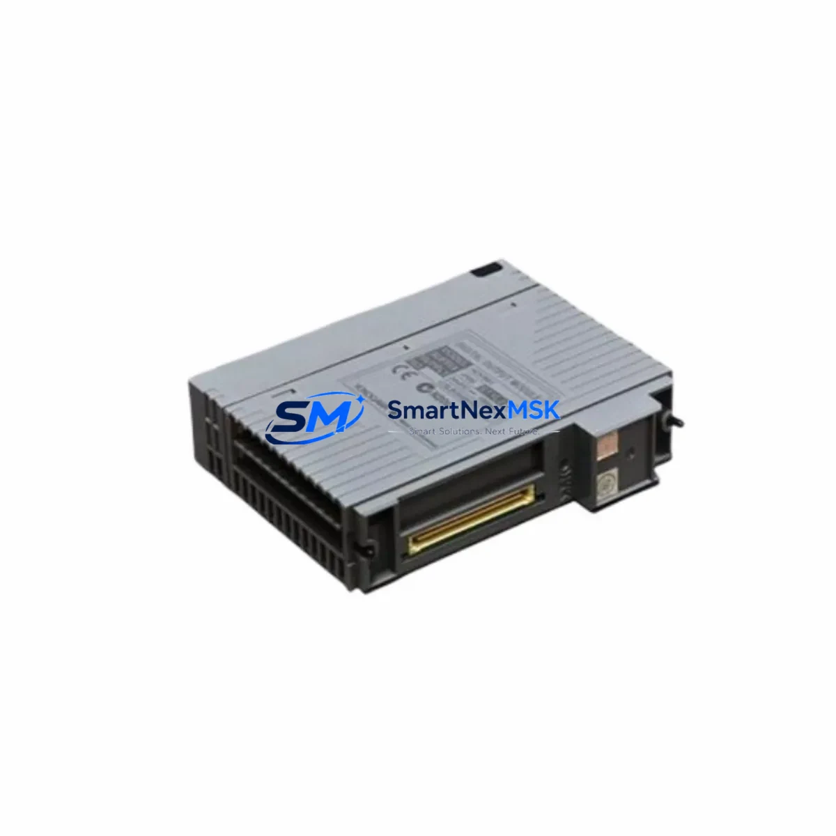
YOKOGAWA NFDV561-P01 Retrofit-Ready Digital Output for CENTUM VP Control Systems
The YOKOGAWA NFDV561-P01 is a 16-channel digital output module engineered for seamless integration into CENTUM VP distributed control systems. As legacy CENTUM CS 3000 and CENTUM VP R4 installations reach end-of-support milestones, plant engineers and system integrators increasingly rely on the NFDV561-P01 as a verified drop-in replacement that preserves existing wiring infrastructure, backplane slot assignments, and control logic without requiring a full system overhaul. Whether you are executing a phased modernization of an aging refinery DCS, upgrading a power plant control cabinet, or restoring a critical production line after an unplanned module failure, the NFDV561-P01 delivers the compatibility and reliability your operation demands.
Upgrade Compatibility Table
| Parameter | NFDV561-P01 (Current) | Legacy / Predecessor | Retrofit Notes |
|---|---|---|---|
| Output Channels | 16 DO (transistor) | 16 DO | Channel count identical; no I/O mapping changes required |
| Backplane Interface | CENTUM VP node bus | CENTUM CS 3000 / VP R4 node bus | Slot-compatible; verify FCU firmware ≥ R10.04 |
| Installation | Standard YOKOGAWA I/O nest | Same nest form factor | No mechanical modification needed |
| Communication | Vnet/IP (Ethernet-based) | Vnet/IP | Protocol fully compatible; no gateway required |
| Replacement Recommendation | Direct replacement for NFDV561 variants | NFDV561, NFDV561-P00 | Confirm P-suffix hardware revision with site documentation |
| Commissioning Focus | Module address, tag assignment, FCU download | Same procedure | Use CENTUM VP Engineering Environment (ENG) for re-download |
| Warranty | 12-Month Warranty — covers manufacturing defects; includes pre-shipment functional test report | ||
Retrofit Planning for Existing Automation Systems
A successful NFDV561-P01 retrofit begins well before the module arrives on site. The first step is a thorough audit of the existing control cabinet: confirm the power supply capacity of the YOKOGAWA PW482 or equivalent 24 VDC field power supply, since adding or replacing DO modules can shift the total current draw on the I/O nest. Cross-reference the terminal block wiring diagrams against the NFDV561-P01 field terminal adapter — typically the TB481 or TB482 — to ensure conductor gauge, shielding, and grounding practices remain compliant with YOKOGAWA installation standards.
Next, review the FCU (Field Control Unit) configuration. The YOKOGAWA FFCS-V or NFCP100 field control processor must be running a firmware version that recognizes the NFDV561-P01 hardware revision. In multi-node architectures, the ESB10D or ESB10S extended station bus coupler may need a firmware refresh to correctly enumerate the replacement module at its assigned slot address. Document the existing module address and I/O tag assignments in the CENTUM VP Engineering Environment before removal — this data is essential for the post-installation FCU application download.
For plants running hybrid architectures that combine CENTUM VP with third-party SCADA or safety systems, verify that the Vnet/IP communication link between the FCU and the HIS (Human Interface Station) remains uninterrupted during the swap. If the site uses a YOKOGAWA STARDOM FCN/FCJ controller for remote I/O expansion, confirm that the DO module replacement does not conflict with any cross-controller interlock logic. HMI faceplates referencing the affected DO tags should be reviewed in CENTUM VP HIS to confirm that alarm setpoints, output limits, and manual override states are preserved after the FCU download.
Where the retrofit involves migrating from an older CENTUM CS 3000 platform, the engineering team should also account for the NFAI141 analog input modules and NFBI143 bus interface modules sharing the same I/O nest, as their configuration files may need to be re-exported and re-imported into the CENTUM VP project database. Keeping a full backup of the FCU application on a dedicated engineering workstation before any hardware change is non-negotiable. All replacement modules supplied by SMARTNEXMSK are pre-tested against YOKOGAWA factory acceptance criteria and ship with a functional test report, supporting a 12-month warranty from the date of delivery.
Downtime Control During System Migration
Minimizing unplanned downtime is the primary concern for any live-plant DCS module replacement. The recommended approach is a hot-standby swap where the process unit is placed in manual control mode at the HIS operator station before the NFDV561-P01 is physically removed. This preserves the last known output states on the field devices — valves, actuators, and relay-driven loads — while the module is exchanged. If the FCU supports redundant I/O, the standby I/O path can maintain field control continuity throughout the swap, reducing the effective control interruption to the FCU application download cycle, typically under 30 seconds for a standard CENTUM VP node.
After installing the NFDV561-P01, perform a slot recognition check in the CENTUM VP Engineering Environment before initiating the FCU download. Confirm that the module address matches the original assignment and that all 16 DO channels are mapped to their correct tag names. Execute the FCU download in online mode where plant conditions permit, then verify each output channel by commanding a test state from the HIS and confirming field device response. Log all commissioning steps in the site maintenance management system to satisfy audit and safety requirements. With proper pre-staging and a structured commissioning checklist, most NFDV561-P01 replacements are completed within a single maintenance window of two to four hours.
Retrofit Support FAQ
Q1: Is the NFDV561-P01 a direct drop-in replacement for the NFDV561-P00?
A: In most CENTUM VP installations, yes. The P01 hardware revision maintains the same backplane connector, channel count, and field terminal adapter footprint as the P00. However, you should verify the FCU firmware version supports the P01 revision code — refer to YOKOGAWA TI 33J01A10-01EN for compatibility matrices. SMARTNEXMSK can provide the module’s hardware revision label and test report prior to shipment on request.
Q2: What wiring changes are required during installation?
A: No wiring changes are typically required when replacing a like-for-like NFDV561 variant. The field terminal adapter (TB481/TB482) remains in place; only the module body is swapped. Confirm that the existing cable shield grounding at the terminal block is intact and that no conductor insulation has degraded, particularly in high-temperature cabinet environments.
Q3: How is compatibility verified before the module ships?
A: Every NFDV561-P01 unit supplied by SMARTNEXMSK undergoes a pre-shipment functional test that validates all 16 DO channels, backplane communication, and power consumption within YOKOGAWA specification limits. A test report is included with each shipment. The 12-month warranty covers manufacturing defects identified during installation or normal operation within the warranty period.
Q4: Can this module be used in a CENTUM CS 3000 system?
A: The NFDV561-P01 is designed for CENTUM VP architecture. While the physical form factor may appear similar to CS 3000 I/O modules, the backplane communication protocol and FCU firmware requirements differ. For CS 3000 applications, please contact SMARTNEXMSK to identify the correct replacement module for your specific FCU and I/O nest configuration.
© 2026 SMARTNEXMSK. All rights reserved.
Original Source: https://smartnexmsk.com
Contact: [email protected] | +86 18259474341



