
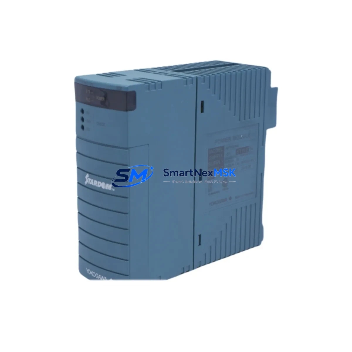
YOKOGAWA NFPW442-50 Retrofit-Ready FCS Power Input Module for CENTUM VP / CS 3000 Control Systems
The YOKOGAWA NFPW442-50 is a 50Hz Field Control Station (FCS) power input module engineered for seamless integration into CENTUM VP and CS 3000 distributed control systems. As legacy DCS installations age and original spare parts become increasingly scarce, the NFPW442-50 serves as a verified drop-in replacement that preserves existing backplane wiring, rack mounting geometry, and firmware-level power management protocols — enabling plant engineers to execute controlled modernization without disrupting live process loops.
Whether you are replacing a failed unit on an emergency basis, executing a planned outage upgrade, or building a strategic spare inventory for a multi-year maintenance contract, the NFPW442-50 is pre-tested, serialized, and shipped with a 12-month warranty covering both component integrity and functional performance under rated load conditions.
Upgrade Compatibility Table
| Parameter | NFPW442-50 Specification | Retrofit Notes |
|---|---|---|
| Input Frequency | 50 Hz | Confirm site power standard before ordering; 60Hz variant is NFPW442-60 |
| Rack / Backplane Interface | CENTUM VP / CS 3000 FCS backplane | Direct slot-in replacement; no backplane adapter required |
| Communication Compatibility | Vnet/IP, Ethernet-based FCS bus | No protocol reconfiguration needed for same-generation FCS nodes |
| Mounting | Standard YOKOGAWA FCS rack (AFV10S / AFV30S) | Verify rack generation; AFV10D racks may require firmware check |
| Replacement Recommendation | Direct replacement for NFPW441-50 (discontinued) | Confirm terminal block pinout matches existing field wiring |
| Commissioning Focus | Power redundancy switchover test | Validate active/standby failover before returning to service |
| Warranty | 12 Months | Covers functional performance under rated operating conditions |
Retrofit Planning for Existing Automation Systems
Successful integration of the NFPW442-50 into an aging CENTUM VP or CS 3000 installation requires a structured pre-replacement audit. Engineers should begin by documenting the existing power distribution architecture within the control cabinet, noting whether the FCS node operates with a single power supply or in a redundant N+1 configuration using a paired NFPW442-50 in the adjacent slot.
Terminal block wiring should be photographed and mapped before any module extraction. The NFPW442-50 uses the same 24VDC bus output topology as its predecessor, but field wiring connected to the NTBP01 or NTBP02 terminal boards must be verified for correct polarity and torque specification. If the existing installation uses an NFPW441-50 (now discontinued), the NFPW442-50 is the designated successor and requires no changes to the terminal board or field cable routing.
For FCS nodes that also house NFAI141 analog input modules, NFDO501 digital output modules, or NFBI143 bus interface cards, the power budget must be recalculated to confirm the NFPW442-50 can sustain the aggregate load across all populated slots. In high-density racks running NFCP701 or NFCP702 FCS controllers alongside multiple I/O modules, a load margin of at least 15% is recommended to accommodate thermal derating at elevated ambient temperatures.
Communication continuity is maintained through the Vnet/IP network interface on the FCS node. The NFPW442-50 does not participate in Vnet/IP addressing directly, but its stable power output is critical to maintaining the uptime of the NFCP701 controller and its associated Vnet/IP port. Any interruption to FCS power during a live migration will cause the node to drop from the Vnet/IP ring, triggering alarms at the HIS (Human Interface Station) and potentially forcing a cold restart of the FCS program. Pre-staging a replacement NFPW442-50 in a bench test environment using a spare AFV10S rack and a YOKOGAWA FieldMate or CENTUM VP Engineering Environment workstation is strongly recommended before on-site installation.
If the retrofit scope extends to upgrading the HMI layer — for example, migrating from a legacy CENTUM CS 3000 HIS running Windows XP to a CENTUM VP HIS on Windows Server — the NFPW442-50 replacement can be coordinated with the HMI migration window to consolidate downtime. During this window, engineers should also audit the NFBM801 bus master module and any installed NFCP701 controller firmware versions to ensure compatibility with the updated HIS software revision.
Downtime Control During System Migration
Minimizing unplanned downtime during a power module replacement is the primary operational concern for any plant running continuous processes. The NFPW442-50 supports hot-standby redundancy when installed in a dual-power configuration, meaning a properly staged replacement can be executed with zero process interruption: the standby module assumes full load while the failed or aging primary is extracted and the new NFPW442-50 is seated and initialized.
For single-supply FCS nodes without redundancy, the replacement window must be coordinated with the process control team to identify the shortest permissible shutdown interval. Typical field experience indicates that a trained technician familiar with CENTUM VP rack architecture can complete a single-module swap — including visual inspection, terminal verification, module seating, and initial power-on self-test — in under 20 minutes. The FCS program stored in the NFCP701 controller’s non-volatile memory is preserved through the power interruption, eliminating the need for program reload from the engineering workstation in most cases.
Before re-energizing, confirm that the NFPW442-50’s LED status indicators cycle through the expected startup sequence: PWR (green), ALM (momentary amber), and RUN (green steady). Any persistent ALM indication after startup requires immediate investigation of the backplane connector seating and input voltage level before the FCS node is returned to automatic control mode. All pre-commissioning checks, including redundancy switchover tests and Vnet/IP ring restoration confirmation, should be documented in the site maintenance log to satisfy ISO 55001 asset management and functional safety audit requirements.
Retrofit Support FAQ
Q1: Is the NFPW442-50 a direct replacement for the discontinued NFPW441-50?
Yes. The NFPW442-50 is the designated successor to the NFPW441-50 within the YOKOGAWA CENTUM VP and CS 3000 FCS power supply family. It shares the same backplane connector, rack slot footprint, and 24VDC output bus, making it a direct mechanical and electrical replacement. No modifications to the terminal board, field wiring, or FCS configuration are required in standard installations.
Q2: What commissioning steps are required after installing the NFPW442-50?
After seating the module, verify input voltage at the terminal block, confirm the PWR and RUN LEDs reach steady green, and — for redundant configurations — perform a manual switchover test to validate that the standby module assumes load correctly. For FCS nodes running NFCP701 or NFCP702 controllers, confirm that the Vnet/IP ring status returns to normal on the HIS overview screen before releasing the node to automatic control.
Q3: Can the NFPW442-50 be used in both CENTUM VP and CS 3000 systems?
Yes, provided the rack generation is compatible. The NFPW442-50 is designed for use in AFV10S and AFV30S FCS racks, which are common to both CENTUM VP and CS 3000 installations. If your site uses older AFV10D racks originally deployed with CS 3000 R3 or earlier, a firmware compatibility check with YOKOGAWA technical support is recommended prior to installation.
Q4: What does the 12-month warranty cover, and how is it claimed?
The 12-month warranty covers manufacturing defects and functional failures under rated operating conditions, including input voltage tolerance, output load regulation, and thermal performance within the specified ambient range. Warranty claims are initiated by contacting our sales team with the module serial number and a description of the failure mode. Replacement units are dispatched within 3 business days for in-warranty claims, and all outgoing units are functionally tested prior to shipment.
© 2026 SMARTNEXMSK. All rights reserved.
Original Source: https://smartnexmsk.com
Contact: [email protected] | +86 18259474341



