
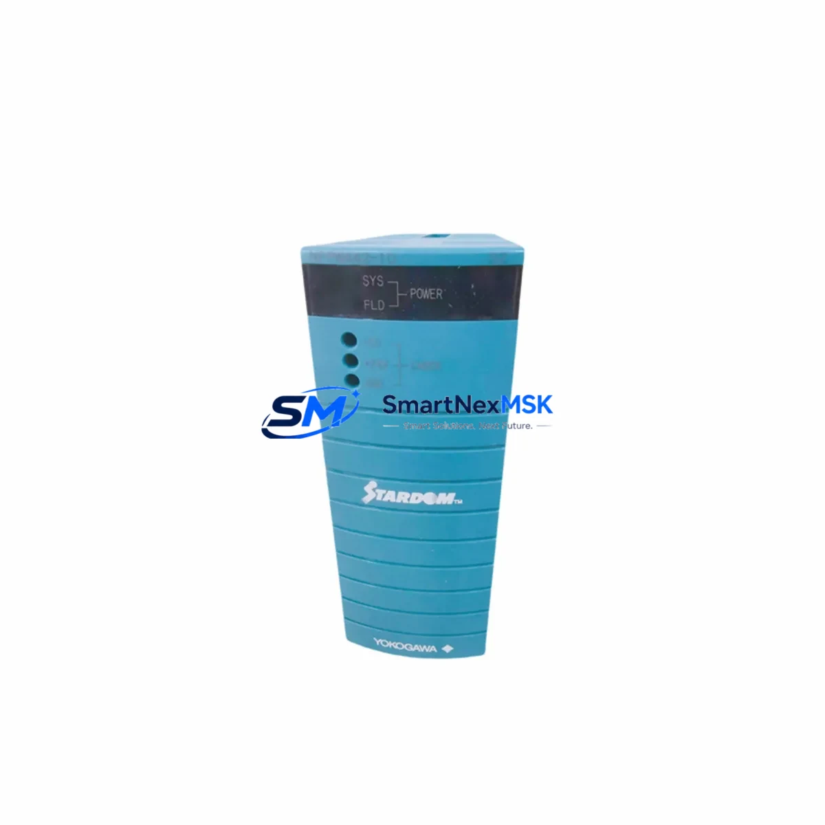
Yokogawa NFPW442-51 Maintenance-Ready Spare CENTUM VP
The Yokogawa NFPW442-51 is an original redundant power supply module engineered for mission-critical DCS environments running CENTUM VP and CS 3000 platforms. As a direct-replacement industrial spare, it is designed to minimize unplanned downtime and restore control system integrity with zero configuration changes. Each unit is tested before shipment and backed by a 12-month warranty, making it a reliable choice for maintenance engineers managing aging automation infrastructure or executing planned overhauls.
Power supply failures are among the most disruptive events in a DCS environment. The NFPW442-51 supports hot-swap redundancy, allowing field technicians to replace a degraded unit without shutting down the entire control loop. For facilities operating CENTUM VP field control stations (FCS) or legacy CS 3000 cabinets, maintaining at least one NFPW442-51 in the spare parts inventory is a recognized best practice for continuous operation and IEC 61511 functional safety compliance.
Spare Maintenance Table
| Parameter | Specification |
|---|---|
| Part Number | NFPW442-51 |
| Brand | Yokogawa Electric Corporation |
| Series Compatibility | CENTUM VP, CS 3000 |
| Module Type | Redundant DCS Power Supply Module |
| Input Voltage | 100–240 V AC, 50/60 Hz (universal input) |
| Output Voltage | 24 V DC regulated |
| Redundancy Support | Yes — hot-swap capable |
| Mounting | DIN rail / FCS cabinet backplane slot |
| Operating Temperature | 0°C to 55°C |
| Storage Temperature | -25°C to 70°C |
| Humidity | 5% to 95% RH, non-condensing |
| Protection Class | IP20 |
| Weight | Approx. 1,310 g |
| Origin | Japan |
| Condition | Original, new or refurbished-to-spec |
| Pre-shipment Test | Yes — functional and load test performed |
| Warranty | 12 Months |
| Maintenance Recommendation | Inspect every 12–18 months; replace at first sign of output ripple or thermal alarm |
Maintenance Planning for Continuous Operation
When replacing the NFPW442-51 in a CENTUM VP or CS 3000 field control station, a thorough inspection of the surrounding power distribution and I/O infrastructure is essential to prevent repeat failures and ensure system stability. Maintenance engineers should treat a power supply replacement as an opportunity for a broader cabinet health check.
Begin by verifying the upstream AC input wiring and terminal blocks — loose connections or corroded terminals on the power distribution rail can cause intermittent supply faults that damage replacement modules prematurely. Inspect the NFPW441 or NFPW442 companion power supply unit if a dual-redundant configuration is in use; a degraded partner module will immediately stress the newly installed NFPW442-51.
Check the NFAI143 or NFAI835 analog input modules powered by this supply rail — voltage sag events can corrupt calibration offsets and trigger nuisance alarms. Similarly, inspect NFDO132 digital output modules for contact wear or blown output fuses, as DO modules draw surge current during actuator switching that can accelerate power supply aging.
For systems with NFCP701 or NFCP702 field control processors, confirm that the processor’s internal diagnostics show no power-related fault history after the swap. Communication modules such as the NFEB103 Vnet/IP interface card should also be checked for link stability, as power interruptions can corrupt firmware states in network interface modules.
Review the NFSV122 or equivalent safety valve interface modules if the FCS is integrated into a safety instrumented system (SIS). Ensure that the 24 V DC bus voltage is within ±2% tolerance after the replacement before re-enabling field outputs. Terminal blocks, fuse holders, and surge protection devices on the 24 V distribution bus should be inspected and replaced if signs of arcing or discoloration are present.
For HMI-connected cabinets, verify that the NFHV100 or equivalent HMI interface module resumes normal communication after power restoration. Maintaining a documented spare parts list that includes the NFPW442-51 alongside its associated I/O modules, communication cards, and fuse sets is the most effective strategy for reducing mean time to repair (MTTR) across the CENTUM VP platform.
Site Replacement Workflow
Step 1 — Pre-replacement verification: Confirm the failed module’s part number against the cabinet label and Yokogawa engineering documentation. Verify that the replacement NFPW442-51 matches the suffix revision (-51) to ensure firmware and hardware compatibility with the installed FCS generation.
Step 2 — Safety isolation: If the system does not support hot-swap in the current configuration, follow the site LOTO (Lockout/Tagout) procedure. For redundant configurations, switch the load to the partner supply before extraction.
Step 3 — Module extraction and installation: Release the module latch, slide out the failed unit, and insert the replacement NFPW442-51 until the connector seats fully. Confirm the status LED transitions from fault to normal within 10 seconds of insertion.
Step 4 — Post-installation checks: Measure output voltage at the 24 V bus test points. Confirm no alarms are active in the CENTUM VP HIS (Human Interface Station). Log the replacement in the site maintenance management system (CMMS) with the module serial number and installation date.
Step 5 — System validation: Run a 15-minute observation period monitoring all I/O modules on the affected FCS segment. Confirm that analog input readings are stable and digital output states match the process controller commands before returning the loop to automatic control.
This workflow is applicable to both planned maintenance windows and emergency breakdown recovery scenarios. The NFPW442-51’s plug-and-play compatibility with existing CENTUM VP and CS 3000 backplanes eliminates the need for re-engineering or firmware re-flashing, significantly reducing replacement time compared to cross-brand alternatives.
Spare Parts Support FAQ
Q1: Is the NFPW442-51 compatible with both CENTUM VP and CS 3000 systems?
Yes. The NFPW442-51 is designed for use across Yokogawa’s CENTUM VP and CS 3000 DCS platforms. It is a direct form-fit-function replacement for the same part number installed in either system generation. Always verify the cabinet slot designation and power bus configuration against the Yokogawa FCS hardware manual before installation.
Q2: What pre-shipment testing is performed on each unit?
Every NFPW442-51 unit undergoes functional power-on testing and output load verification prior to dispatch. Units are inspected for physical integrity, connector condition, and correct output voltage regulation. A test report is available upon request for quality-critical procurement processes.
Q3: How should the NFPW442-51 be stored as a long-term spare?
Store in original anti-static packaging in a dry, temperature-controlled environment (10°C–30°C, <70% RH). Avoid exposure to direct sunlight or corrosive atmospheres. For long-term storage exceeding 24 months, perform a power-on functional check before deployment to verify capacitor health and output stability.
Q4: What is the warranty coverage and what does it include?
The NFPW442-51 is covered by a 12-month warranty from the date of shipment. The warranty covers manufacturing defects and functional failures under normal operating conditions. It does not cover damage resulting from incorrect installation, overvoltage events, or unauthorized modification. Warranty claims are processed with return merchandise authorization (RMA) and include repair or replacement at no additional cost.
© 2026 SMARTNEXMSK. All rights reserved.
Original Source: https://smartnexmsk.com
Contact: [email protected] | +86 18259474341



