
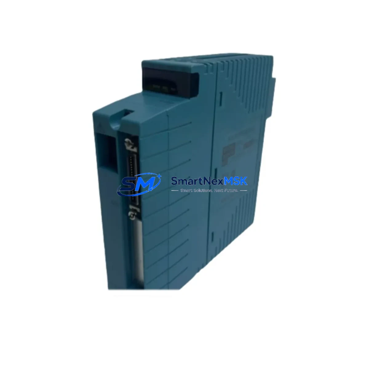
YOKOGAWA NFSB100-S50 Spare for STARDOM Automation: Fieldbus Replacement & Downtime Risk Control
The YOKOGAWA NFSB100-S50 is an original Foundation Fieldbus (FF H1) communication module designed for the STARDOM FCN/FCJ autonomous controller platform. In industrial process automation environments — including oil & gas, chemical, power generation, and water treatment — this module serves as the critical interface between the controller and field instruments such as pressure transmitters, flow meters, and control valves operating on the FF H1 segment. When this module fails or degrades, the entire fieldbus segment loses communication, triggering process alarms, loss of control, and unplanned shutdown. Maintaining a verified spare of the NFSB100-S50 in your local inventory is a fundamental requirement for any site running STARDOM-based control systems.
This listing provides an original YOKOGAWA NFSB100-S50 spare module, sourced from authorized supply channels, individually tested before shipment, and backed by a 12-month warranty. Each unit is verified for firmware compatibility and physical integrity prior to dispatch, ensuring it is ready for immediate installation upon arrival.
Spare Maintenance Table
| Parameter | Specification / Detail |
|---|---|
| Part Number | NFSB100-S50 |
| Brand | YOKOGAWA |
| Compatible Platform | STARDOM FCN / FCJ Autonomous Controller |
| Communication Protocol | Foundation Fieldbus H1 (FF H1) |
| Module Type | Fieldbus Communication Module |
| Segment Support | Up to 2 FF H1 segments per module (model-dependent) |
| Power Supply | Supplied via FCN/FCJ backplane (internal bus) |
| Operating Temperature | 0°C to 55°C (standard industrial range) |
| Mounting | FCN/FCJ module slot (hot-swap capable with proper procedure) |
| Origin | Japan |
| Condition | Original, new or refurbished-to-spec, tested before shipment |
| Warranty | 12 Months from date of shipment |
| Shipping | EMS / DHL / FedEx — global delivery, export documentation available |
| Compatibility Verification | Confirmed against STARDOM FCN/FCJ hardware revision list |
| Maintenance Recommendation | Replace at first sign of segment communication loss; keep one spare per active FF segment |
Maintenance Planning for Continuous Operation
When a maintenance or reliability engineer schedules a planned inspection or responds to a fieldbus segment fault on a STARDOM FCN/FCJ system, the NFSB100-S50 is rarely the only component that requires attention. A thorough maintenance review of the control cabinet and associated field wiring should include the following components to prevent repeat failures and ensure full segment restoration:
The FCN-500 or FCJ power supply module should be checked for output voltage stability, as an under-voltage condition on the backplane bus can cause intermittent communication faults that mimic a failed NFSB100-S50. Alongside this, the FCN CPU module (e.g., NFCP100) should be inspected for firmware version compatibility with the fieldbus module being replaced, since mismatched firmware revisions can prevent segment initialization after a module swap.
The FF H1 segment terminator — typically a passive RC terminator installed at each end of the fieldbus cable — is a common source of segment instability and should be tested or replaced as part of any NFSB100-S50 maintenance event. Similarly, the fieldbus power conditioner supplying the H1 segment should be verified for correct output voltage (typically 24–32 VDC on the segment) and ripple characteristics.
For sites using YOKOGAWA EJX or EJA series transmitters on the same FF H1 segment, device descriptors (DDs) and function block configurations should be backed up before the module swap and re-verified after restoration. The STARDOM FAST/TOOLS SCADA or CENTUM VP integration should also be checked to confirm that the OPC or Modbus communication path to the FCN/FCJ controller remains intact after the module replacement.
In the control cabinet, DIN rail terminal blocks and cable shield grounding connections on the FF H1 wiring should be inspected for corrosion or loosening, particularly in high-humidity or high-vibration environments. If the site uses signal isolators or fieldbus barriers (such as YOKOGAWA or P+F models) for intrinsically safe installations, these should be tested for correct impedance and power delivery to the segment. Finally, the FCN I/O modules sharing the same backplane — including analog input modules such as the AAI143 or AAI543 — should be confirmed as fully operational to rule out backplane communication issues that could be misattributed to the fieldbus module.
Site Replacement Workflow
Step 1 — Pre-replacement preparation: Download the current NFSB100-S50 configuration and FF device parameters using YOKOGAWA’s STARDOM Engineering Tool or FieldMate. Record all segment device addresses, function block assignments, and link schedules. This backup is essential for restoring the segment to its pre-fault state without re-engineering.
Step 2 — Safe module removal: Place the affected FF H1 segment in manual control mode at the SCADA or DCS level to prevent process upsets during the swap. If the FCN/FCJ supports hot-swap for the NFSB100-S50 slot, follow the documented hot-swap procedure. If not, schedule a brief controlled shutdown of the segment. Remove the faulty module and inspect the backplane connector for bent pins or contamination.
Step 3 — Spare installation and configuration restore: Insert the replacement NFSB100-S50 into the correct slot. Power up the module and confirm that the FCN/FCJ controller recognizes it. Restore the saved configuration using the engineering tool. Verify that all FF devices on the segment re-establish communication and that function blocks resume scheduled execution.
Step 4 — Functional verification: Confirm process variable readings from all FF instruments on the segment match expected values. Check for any diagnostic alarms on the fieldbus segment. Return the segment to automatic control mode and monitor for 15–30 minutes to confirm stable operation.
Step 5 — Spare replenishment: Log the replacement event in your CMMS and initiate a purchase order for a new NFSB100-S50 spare to restore your on-site buffer stock. Sites with multiple FCN/FCJ controllers should maintain at least one NFSB100-S50 spare per installed system.
Spare Parts Support FAQ
Q1: Is this NFSB100-S50 compatible with both FCN and FCJ controllers?
Yes. The NFSB100-S50 is designed for the STARDOM FCN/FCJ platform and is compatible with both controller variants. Compatibility should be confirmed against your specific FCN/FCJ hardware revision and firmware version using YOKOGAWA’s compatibility matrix or by consulting your engineering documentation. We can assist with compatibility verification prior to order confirmation.
Q2: How is the module tested before shipment?
Each NFSB100-S50 unit undergoes functional testing prior to dispatch, including power-on verification, communication interface check, and physical inspection of connectors and housing. A test report is available upon request. Units are packed in anti-static packaging with protective foam to prevent transit damage.
Q3: What does the 12-month warranty cover?
The 12-month warranty covers manufacturing defects and functional failures under normal operating conditions. It does not cover damage caused by incorrect installation, overvoltage, physical impact, or use outside the specified environmental range. In the event of a warranty claim, we provide replacement or repair with priority processing to minimize your downtime.
Q4: Can you supply multiple units for long-term spare parts inventory?
Yes. We support bulk spare parts orders for maintenance departments and MRO procurement teams. Long-term supply agreements are available for sites requiring ongoing access to YOKOGAWA STARDOM spare modules. Contact us to discuss quantity pricing, lead times, and consignment stock arrangements.
© 2026 SMARTNEXMSK. All rights reserved.
Original Source: https://smartnexmsk.com
Contact: [email protected] | +86 18259474341



