
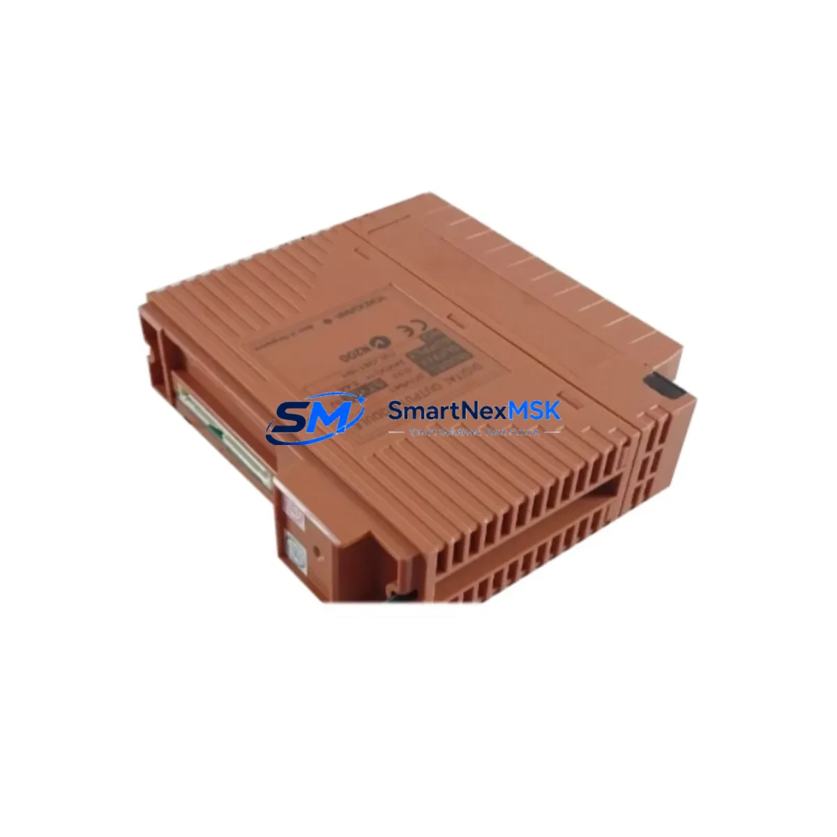
Yokogawa SDV541-S33-S2 Retrofit-Ready Signal Conditioner for CENTUM VP Control Systems
The Yokogawa SDV541-S33-S2 is a signal conditioning module designed for seamless integration into CENTUM VP distributed control system architectures. As legacy CENTUM CS 3000 and early CENTUM VP installations reach end-of-service milestones, the SDV541-S33-S2 has become a critical component in plant-wide retrofit programs, enabling engineers to maintain signal integrity across analog I/O loops without redesigning the control cabinet or rewriting existing function block logic. Whether you are replacing a failed unit, upgrading a discontinued module, or expanding an existing I/O subsystem, the SDV541-S33-S2 delivers verified drop-in compatibility with standard Yokogawa field control station backplanes.
This module is fully compatible with the Yokogawa FCS (Field Control Station) platform, including the AFV10S and AFV30S station types commonly deployed in refinery, chemical, and power generation applications. It mounts directly onto standard Yokogawa I/O nest assemblies and interfaces with the system bus without requiring firmware reconfiguration when replacing a like-for-like unit. For engineers managing a brownfield upgrade, this means the SDV541-S33-S2 can be swapped into an existing slot while preserving the original tag assignments, channel scaling parameters, and alarm setpoints stored in the CENTUM VP engineering database.
Upgrade Compatibility Table
| Parameter | Detail |
|---|---|
| Compatible Platform | Yokogawa CENTUM VP, CENTUM CS 3000 (with adapter verification) |
| Module Type | Signal Conditioning Module (Analog Input/Output) |
| Backplane Interface | Standard Yokogawa I/O nest — direct slot replacement |
| Terminal Wiring | Compatible with existing field wiring; verify terminal block pitch before installation |
| Communication Protocol | Yokogawa internal V-net/IP or Vnet bus (station-dependent) |
| Replacement Compatibility | Drop-in for SDV541-S33/S2 and functionally equivalent discontinued variants |
| Installation Requirement | No hardware modification required for like-for-like swap; confirm module address via CENTUM VP builder |
| Commissioning Note | Reload tag configuration from engineering database; verify channel scaling and alarm limits post-swap |
| Warranty | 12 months from date of shipment — covers manufacturing defects and functional failure under normal operating conditions |
Retrofit Planning for Existing Automation Systems
A successful retrofit begins well before the module arrives on site. Engineers should first audit the existing I/O nest to confirm available slot positions and verify that the nest firmware revision is compatible with the SDV541-S33-S2 hardware revision. In multi-nest configurations using the Yokogawa ANB10S or ANB11S node bus adapters, confirm that the node address assigned to the target slot does not conflict with other modules already registered in the CENTUM VP system builder. If the installation involves a Yokogawa ESB bus coupler or an RIO (Remote I/O) node, additional latency and address mapping checks are required before the module is powered on.
Field wiring preparation is equally important. The SDV541-S33-S2 uses a standard marshalling terminal arrangement, but engineers replacing older CENTUM CS 3000 modules such as the AAI141-S or AAI543-S should cross-reference the terminal assignment drawings to confirm that signal polarity, shield grounding, and loop power configuration match the new module’s input specifications. In applications where the existing Yokogawa MTL or P&F isolator barriers are wired in series, verify that the combined loop resistance remains within the acceptable range for the SDV541-S33-S2 input impedance.
For sites running Yokogawa CENTUM VP R5 or R6, the module registration process is handled through the CENTUM VP engineering environment. After physical installation, open the hardware configuration view, assign the correct module type to the target slot, and perform a download to the FCS. If the replacement is part of a broader I/O expansion project — for example, adding new measurement points alongside a Yokogawa AAI835-S multi-channel analog input module or integrating a Yokogawa AMM12S math function module — plan the download sequence carefully to avoid disrupting active control loops. Where possible, use the CENTUM VP online change function to minimize the impact on running processes.
Power budget verification is a frequently overlooked step in retrofit planning. Each I/O nest draws power from the Yokogawa PW481 or PW482 power supply unit. Adding the SDV541-S33-S2 to a partially populated nest increases the total current draw; confirm that the installed power supply has sufficient headroom before proceeding. In cabinets where the power supply is already near capacity, consider replacing the PW481 with a higher-rated unit or redistributing modules across nests to balance the load. Similarly, if the retrofit involves adding a Yokogawa ALR111 alarm module or a Yokogawa AIP588 communication interface module to the same cabinet, recalculate the total power budget before finalizing the bill of materials.
HMI screen updates should be coordinated with the I/O retrofit schedule. If the SDV541-S33-S2 is replacing a module whose tag names or channel numbers have changed, update the corresponding faceplates and trend displays in the Yokogawa CENTUM VP HIS (Human Interface Station) to reflect the new configuration. Operators should be briefed on any temporary changes to alarm presentation during the commissioning window.
Downtime Control During System Migration
Minimizing unplanned downtime is the primary concern in any live-system module replacement. For the SDV541-S33-S2, the recommended approach is a hot-standby swap where the process unit supports redundant I/O paths. In non-redundant configurations, coordinate the replacement with the operations team to schedule a brief controlled shutdown of the affected measurement loop, isolate the field device at the junction box, and complete the module swap within a defined maintenance window.
Before removing the existing module, export the current tag configuration from the CENTUM VP engineering database and save a backup of the FCS project to a secure location. This ensures that if the new module requires a full download rather than an online change, the original control logic — including PID tuning parameters, interlock conditions, and sequence function chart steps — can be restored without manual re-entry. After installing the SDV541-S33-S2, perform a channel-by-channel loop check using a calibrated signal source to verify that each input reads correctly at 0%, 50%, and 100% of the engineering range before returning the loop to automatic control.
For multi-module replacements carried out as part of a scheduled turnaround, consider pre-staging and bench-testing each SDV541-S33-S2 unit against a portable CENTUM VP test environment before bringing it to the field. This approach catches configuration errors and hardware faults before installation, reducing the risk of extended downtime caused by a defective module discovered during commissioning. All units supplied by SMARTNEXMSK are subject to pre-shipment functional testing and are shipped with a test report confirming channel accuracy and communication integrity.
Retrofit Support FAQ
Q: Is the SDV541-S33-S2 a direct replacement for discontinued Yokogawa signal conditioning modules in CENTUM CS 3000 systems?
A: The SDV541-S33-S2 is designed for CENTUM VP platforms. Compatibility with CENTUM CS 3000 depends on the specific nest and bus revision. We recommend providing your existing module part number and FCS hardware revision so our technical team can confirm the replacement path before you order.
Q: What wiring changes are required when installing the SDV541-S33-S2 in place of an older module?
A: In most like-for-like replacements, no wiring changes are required. However, you should verify terminal block pitch, loop power polarity, and shield grounding against the SDV541-S33-S2 installation manual. If the original module used a different terminal arrangement, a wiring adapter or re-termination at the marshalling panel may be necessary.
Q: How do I verify module address and channel configuration after installation?
A: After physical installation, open the CENTUM VP hardware configuration builder, confirm the module type assigned to the target slot matches SDV541-S33-S2, and perform a configuration download to the FCS. Use the CENTUM VP diagnostic view to verify that all channels report a healthy status before enabling automatic control.
Q: What does the 12-month warranty cover, and what is the process for a warranty claim?
A: The 12-month warranty covers manufacturing defects and functional failure under normal operating conditions from the date of shipment. To initiate a warranty claim, contact [email protected] with your order number, a description of the fault, and any available diagnostic data. We will arrange a replacement or repair within the warranty period at no additional cost.
© 2026 SMARTNEXMSK. All rights reserved.
Original Source: https://smartnexmsk.com
Contact: [email protected] | +86 18259474341



