
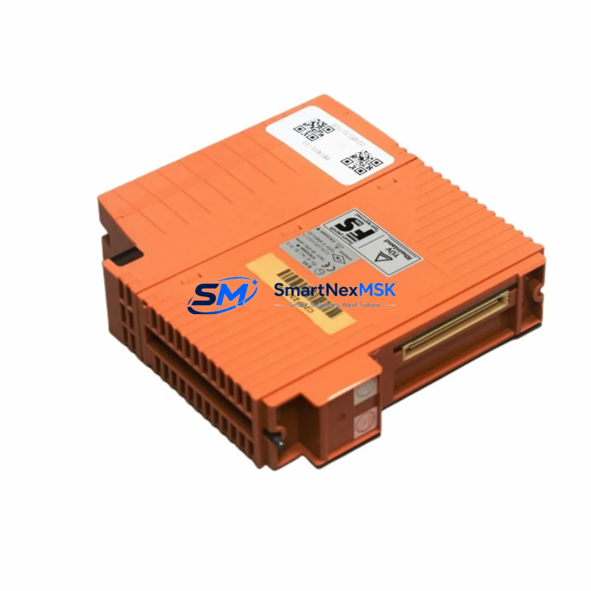
YOKOGAWA SEC401-11 Retrofit-Ready Bus Coupler for CENTUM VP Control Systems
The YOKOGAWA SEC401-11 is a Bus Coupler Module engineered for seamless integration within CENTUM VP distributed control system architectures. As legacy CENTUM CS 3000 and earlier CENTUM VP field control stations approach end-of-life, the SEC401-11 has become a critical component in brownfield retrofit projects, enabling engineers to extend operational life, migrate I/O subsystems, and maintain process continuity without full-system replacement. Whether you are sourcing a direct drop-in replacement for a failed unit or planning a phased control system upgrade, the SEC401-11 delivers the compatibility, reliability, and documentation support that industrial automation teams require.
In retrofit scenarios, the SEC401-11 interfaces directly with YOKOGAWA’s Vnet/IP and ESB (Enhanced Serial Backplane) communication infrastructure. Engineers replacing an existing bus coupler must verify backplane slot assignment, node address configuration, and ESB segment topology before installation. The module’s terminal block layout and wiring pinout are consistent with earlier SEC401 series variants, significantly reducing rewiring time during scheduled maintenance windows or emergency replacements. When paired with the FCS (Field Control Station) chassis — such as the AFV10D or AFV30D — the SEC401-11 maintains full backward compatibility with existing I/O module populations, including AI, AO, DI, and DO cards already installed in the field.
Upgrade Compatibility Table
| Parameter | Details |
|---|---|
| Model | YOKOGAWA SEC401-11 |
| Function | Bus Coupler Module for ESB / Vnet/IP |
| Compatible Platform | CENTUM VP, CENTUM CS 3000 (with engineering review) |
| Backplane Interface | ESB (Enhanced Serial Backplane) |
| Communication Protocol | Vnet/IP (100 Mbps Ethernet-based) |
| Installation Type | DIN-rail / FCS chassis slot mount |
| Wiring Compatibility | Matches SEC401 series terminal layout; no rewiring required in most cases |
| Replacement Recommendation | Direct replacement for SEC401-11; cross-reference SEC401-10 with engineering sign-off |
| Commissioning Notes | Node address DIP switch must match original configuration; ESB segment scan required post-swap |
| Warranty | 12 Months — covers manufacturing defects, functional failure under normal operating conditions |
Retrofit Planning for Existing Automation Systems
A successful SEC401-11 retrofit begins well before the module arrives on site. Project engineers should pull the existing FCS configuration from YOKOGAWA’s Engineering Environment (ENG) software and document the current ESB segment map, including all connected I/O modules such as AAI141-S analog input cards, AAI543-H analog output cards, ADV151-P digital input modules, and ADV551-P digital output modules. Each of these I/O cards communicates through the bus coupler, so any interruption to the SEC401-11’s ESB link will affect the entire I/O subsystem downstream.
Power supply integrity is a prerequisite for a clean swap. The FCS chassis typically draws regulated 24 VDC from a dedicated power supply module — commonly the PW481 or PW482 — and engineers should confirm that the power budget accommodates the SEC401-11’s current draw alongside all populated I/O slots. Insufficient power headroom is a frequent cause of intermittent faults after module replacement and is often misdiagnosed as a coupler defect.
For sites running CENTUM CS 3000 that are migrating toward CENTUM VP, the SEC401-11 plays a transitional role. The migration path typically involves upgrading the FCS chassis to an AFV30D or AFV10D unit, retaining existing field wiring and marshalling cabinets, and replacing the bus coupler and communication modules — such as the CP451-10 or CP461-50 controller processor cards — while preserving the original I/O wiring. This approach minimizes capital expenditure and avoids the cost and risk of full field rewiring.
HMI integration must also be validated during retrofit planning. YOKOGAWA HIS (Human Interface Station) screens built on CENTUM VP’s HMI Builder reference I/O tag addresses that are tied to specific FCS node numbers and module slot positions. If the SEC401-11 replacement changes the ESB segment structure or node addressing, HMI faceplates and alarm configurations may require re-mapping. Coordination between the DCS engineer and the HMI configuration team is essential to avoid display discrepancies after restart.
Communication link verification is the final pre-commissioning step. The Vnet/IP network connecting the FCS to the HIS and ENG stations should be tested for packet loss and latency before the replacement module is brought online. Network switches in the control room — often managed industrial Ethernet switches on a dedicated VLAN — should be confirmed as operational, and the Vnet/IP redundancy pair should be checked to ensure automatic failover is active.
Downtime Control During System Migration
Minimizing process downtime during a SEC401-11 replacement requires a structured hot-swap or cold-swap protocol depending on the FCS redundancy configuration. For redundant FCS installations, the standby controller can assume full process control while the primary FCS chassis undergoes the bus coupler swap, reducing effective downtime to the switchover interval — typically under 30 seconds for a well-maintained CENTUM VP redundancy pair.
Before initiating the swap, the existing control logic should be backed up from the ENG station using YOKOGAWA’s Engineering Environment download function. This preserves all function block definitions, loop tuning parameters, interlock logic, and sequence control programs. The backup should be verified against the last known-good configuration file and stored on an isolated engineering workstation — not on the live network — to prevent accidental overwrite.
During the physical swap, field operators should place affected control loops in manual mode at the HIS to prevent process upsets caused by I/O signal interruption. Once the SEC401-11 is seated and the ESB link is re-established, a systematic loop check — starting with critical process variables such as flow, pressure, and temperature — should be performed before returning loops to automatic control. The entire recommissioning sequence, from module insertion to loop handback, can typically be completed within a two-hour maintenance window for a single FCS chassis.
For non-redundant FCS sites, a planned shutdown window is required. In these cases, pre-staging the replacement SEC401-11, pre-configuring node address DIP switches to match the original unit, and preparing a commissioning checklist in advance can compress the actual downtime to the minimum necessary for safe module exchange and system restart.
Retrofit Support FAQ
Q1: Is the SEC401-11 a direct drop-in replacement for the SEC401-10?
In most CENTUM VP installations, the SEC401-11 is backward compatible with the SEC401-10 slot position and wiring. However, firmware revision differences may require an ENG station configuration download after replacement. Always verify the ESB segment address and confirm compatibility with your specific FCS chassis revision before ordering.
Q2: What commissioning steps are required after installing the SEC401-11?
After physical installation, confirm the node address DIP switch matches the original module’s setting. Perform an ESB segment scan from the ENG station to verify the coupler is recognized. Check all downstream I/O module status indicators, then perform a loop check on all connected analog and digital channels before returning to automatic control.
Q3: Does the SEC401-11 support HART pass-through for field instruments?
HART pass-through capability depends on the connected I/O module type, not the bus coupler itself. The SEC401-11 passes all ESB data transparently; HART communication is handled at the AI/AO module level (e.g., AAI141-S with HART support). Confirm your I/O module model supports HART before planning instrument asset management integration.
Q4: What does the 12-month warranty cover?
All SEC401-11 units supplied by SMARTNEXMSK carry a 12-month warranty covering manufacturing defects and functional failure under normal operating conditions. Each unit undergoes pre-shipment functional testing including ESB communication verification and power-on self-test. Warranty claims are supported by our technical team with replacement dispatch within 5 business days upon confirmed fault diagnosis.
© 2026 SMARTNEXMSK. All rights reserved.
Original Source: https://smartnexmsk.com
Contact: [email protected] | +86 18259474341



