
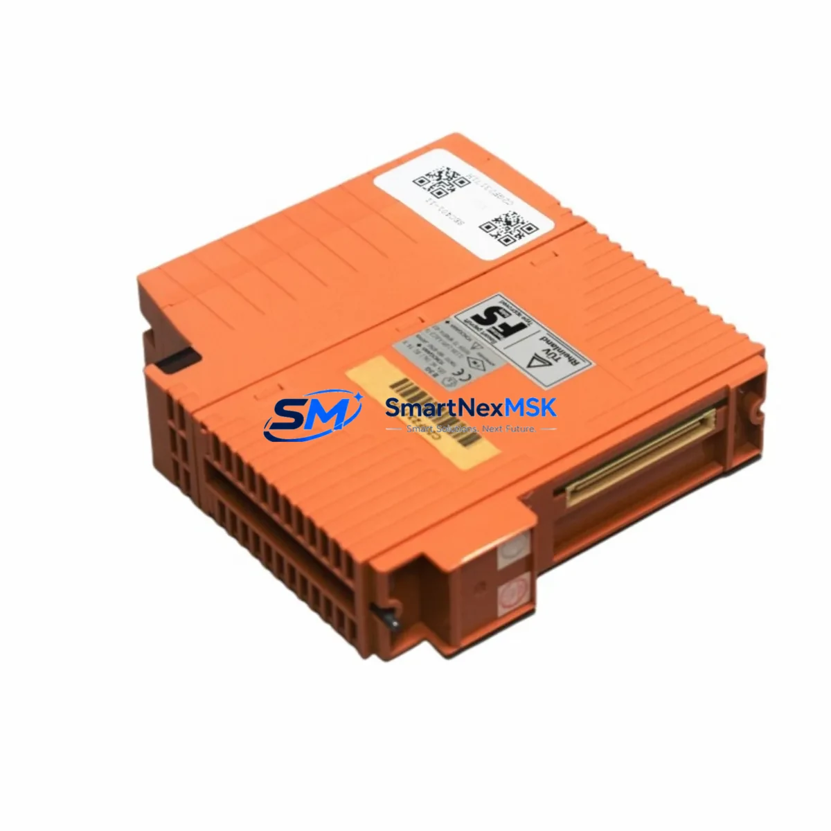
YOKOGAWA SEC401-51 S3 Retrofit-Ready ESB Bus Coupler for CENTUM CS/VP Control Systems
The YOKOGAWA SEC401-51 S3 is an ESB (Enhanced Signal Bus) Bus Coupler module designed for seamless integration into YOKOGAWA CENTUM CS and CENTUM VP Distributed Control System (DCS) architectures. As legacy CENTUM CS installations approach end-of-life and spare part availability tightens, the SEC401-51 S3 has become a critical retrofit component for engineers tasked with sustaining production continuity, upgrading aging control cabinets, and migrating I/O infrastructure without full system replacement.
SMARTNEXMSK maintains verified stock of the SEC401-51 S3, sourced from authorized industrial channels, pre-tested prior to shipment, and covered by a 12-month warranty. Each unit is inspected for firmware revision compatibility, backplane connector integrity, and ESB communication handshake performance before dispatch.
Upgrade Compatibility Table
| Parameter | Details |
|---|---|
| Module Model | SEC401-51 S3 |
| Manufacturer | YOKOGAWA Electric Corporation |
| Compatible Systems | CENTUM CS, CENTUM CS 3000, CENTUM VP (R4.x / R5.x / R6.x) |
| Module Function | ESB Bus Coupler — connects field control stations to the ESB highway |
| Backplane Interface | ESB bus slot; compatible with RIO (Remote I/O) node enclosures |
| Installation Requirement | Mounts into standard YOKOGAWA RIO node chassis; no mechanical modification required |
| Power Supply Compatibility | Powered via backplane from PW481 or PW482 power supply modules |
| Communication Protocol | ESB (Enhanced Signal Bus) — proprietary YOKOGAWA high-speed field bus |
| Replacement Compatibility | Direct replacement for SEC401-51 S1 / S2 revisions in most configurations |
| Commissioning Note | Module address must be verified against FCS (Field Control Station) node configuration in CENTUM Engineering Environment (ENG) |
| Warranty | 12 months from date of shipment — covers manufacturing defects and communication faults |
Retrofit Planning for Existing Automation Systems
Replacing the SEC401-51 S3 within an operational CENTUM CS or CENTUM VP system requires careful pre-migration planning. The ESB bus coupler sits at the heart of the remote I/O communication chain, bridging the Field Control Station (FCS) — typically an FFCS-V or LFCS-V controller — to the distributed I/O nodes installed across the plant floor or control cabinet.
Before initiating the swap, engineers should audit the existing RIO node enclosure to confirm slot assignment and verify that the replacement SEC401-51 S3 carries the correct hardware revision (S3) for the installed CENTUM VP software release. In CENTUM CS 3000 environments running R3.x, the S2 revision was standard; upgrading to S3 may require a minor configuration acknowledgment in the CENTUM Engineering Environment (ENG) builder tool, but no re-download of the FCS program is typically required.
Power budget verification is essential. The PW481 or PW482 power supply modules feeding the RIO node must have sufficient headroom to support the SEC401-51 S3 alongside co-installed I/O modules such as the AAI141-S analog input module, ADV151-P digital input module, or ADA161-S analog output module. A power margin of at least 15% above calculated load is recommended to prevent bus instability during startup transients.
Terminal wiring on the SEC401-51 S3 follows the standard ESB node connector pinout. If the existing installation uses TB801 terminal bases or marshalling panels, no rewiring is required — the coupler connects directly to the backplane. For installations where the original coupler was mounted with a KS1 cable assembly for extended-reach ESB segments, confirm cable length and signal integrity before powering the new module.
In multi-node ESB configurations, each bus coupler carries a unique node address set via hardware DIP switches or rotary selectors on the module face. This address must match the node definition in the FCS builder. Mismatched addresses will cause the node to appear offline in the CENTUM VP HIS (Human Interface Station) and trigger ESB communication alarms. Always photograph or document the existing address setting before removal.
For sites also upgrading their HMI layer — migrating from legacy CENTUM CS HIS workstations to CENTUM VP R6.x — the SEC401-51 S3 is fully compatible with the updated FCS firmware, ensuring that HMI faceplates, trend displays, and alarm configurations remain intact without graphic re-engineering.
If the retrofit scope includes communication protocol migration — for example, adding Vnet/IP connectivity alongside the existing ESB highway — the SEC401-51 S3 continues to serve the ESB segment while the FCS controller handles protocol bridging internally. No additional gateway hardware is required at the bus coupler level.
Downtime Control During System Migration
Minimizing unplanned downtime is the primary concern when replacing an ESB bus coupler in a live production environment. The SEC401-51 S3 supports hot-swap replacement in CENTUM VP systems configured with redundant ESB paths — where a primary and secondary bus coupler pair is installed in the same RIO node. In this configuration, the standby coupler maintains ESB communication while the faulty unit is removed and the replacement SEC401-51 S3 is inserted, eliminating process interruption entirely.
For non-redundant ESB node configurations — common in older CENTUM CS installations — a controlled maintenance window is required. The recommended procedure is to place the affected FCS loop in manual mode via the HIS operator station, isolate the RIO node from the ESB highway using the engineering console, perform the physical swap, restore the ESB link, and verify all I/O points return to their pre-swap states before releasing loops back to automatic control. This sequence typically takes 15–30 minutes per node when spare modules are on-site and pre-tested.
SMARTNEXMSK recommends requesting a pre-shipment function test report with each SEC401-51 S3 order. This document confirms ESB communication handshake, power consumption within spec, and hardware revision, allowing your commissioning team to proceed with confidence and reducing on-site diagnostic time. Units are dispatched from Xiamen with ESD-protective packaging and are ready for immediate installation upon arrival.
Maintaining a cold-standby SEC401-51 S3 in your site spare parts inventory is strongly advised for critical process lines. Given the discontinuation trajectory of CENTUM CS-era components, procurement lead times for field-sourced units can extend to 8–16 weeks. SMARTNEXMSK maintains buffer stock to support urgent same-week dispatch requirements.
Retrofit Support FAQ
Q1: Is the SEC401-51 S3 a direct drop-in replacement for the SEC401-51 S1 or S2?
In most CENTUM CS 3000 and CENTUM VP installations, yes. The S3 hardware revision is backward-compatible with S1 and S2 slot positions and backplane connectors. The only action required is to confirm the node address setting matches the original unit and acknowledge the hardware revision change in the CENTUM ENG builder if prompted. No FCS program re-download is required in standard configurations.
Q2: What commissioning checks are required after installing the SEC401-51 S3?
After physical installation, verify ESB node status in the CENTUM VP System View — the node should transition from “Offline” to “Online” within 30–60 seconds of power-up. Confirm all I/O modules in the node (analog inputs, digital outputs, etc.) report correct process values. Check the FCS alarm summary for any ESB communication errors. If the node address was correctly set and power supply margins are adequate, no further intervention is typically needed.
Q3: Can the SEC401-51 S3 be used in a CENTUM VP R6.x system that has been upgraded from CENTUM CS?
Yes. The SEC401-51 S3 is compatible with CENTUM VP R4.x through R6.x. Migrated systems that retain the original ESB field bus infrastructure can continue using SEC401-51 S3 couplers without hardware changes to the I/O layer. Only the FCS controller and HIS software layers require upgrading during a CENTUM CS to CENTUM VP migration.
Q4: What does the 12-month warranty cover, and what is the return process?
The 12-month warranty covers manufacturing defects, ESB communication failures attributable to the module, and hardware faults confirmed by functional testing. It does not cover damage from incorrect installation, overvoltage, or physical impact. To initiate a warranty claim, contact SMARTNEXMSK at [email protected] with your order reference and a description of the fault. Replacement units are dispatched upon fault confirmation, with return shipping coordinated by our technical team.
© 2026 SMARTNEXMSK. All rights reserved.
Original Source: https://smartnexmsk.com
Contact: [email protected] | +86 18259474341



