
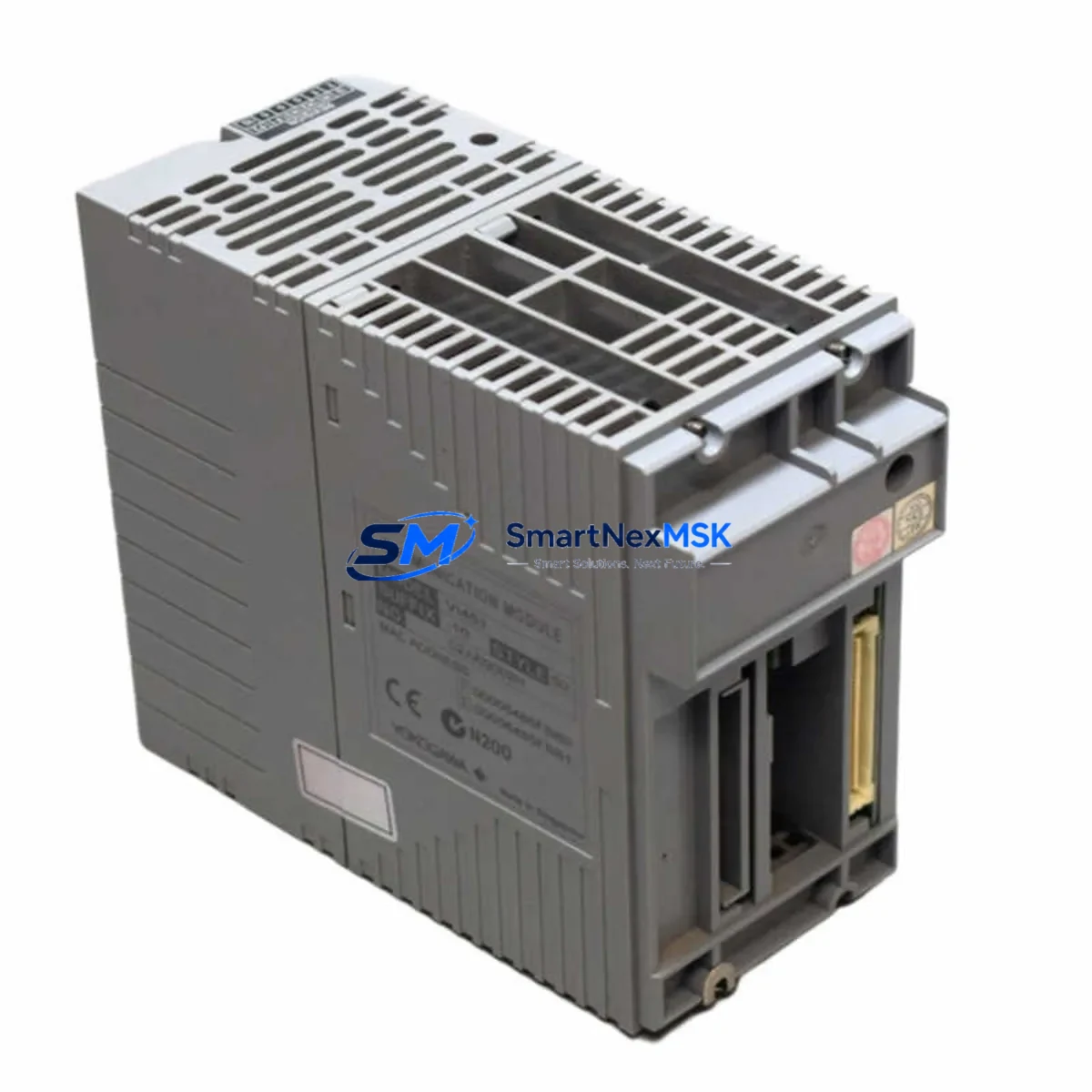
Yokogawa VI451-10 Retrofit-Ready Ethernet Module for STARDOM FCN/FCJ Control Systems
The Yokogawa VI451-10 is a high-performance Ethernet communication module engineered for the STARDOM FCN and FCJ autonomous controller platform. As legacy FCN/FCJ installations approach end-of-support milestones, the VI451-10 has become the preferred retrofit solution for engineers tasked with modernizing distributed control architectures without replacing the entire control cabinet. Whether you are migrating from an older VI401 or VI411 communication card, expanding I/O capacity on an existing FCN-RTU rack, or bridging a legacy serial fieldbus to a modern Ethernet backbone, the VI451-10 delivers the compatibility and reliability that industrial retrofit projects demand.
Designed to slot directly into the standard FCN/FCJ backplane, the VI451-10 supports Modbus TCP, OPC-UA, and FF-HSE protocols, making it compatible with a broad range of SCADA platforms, historian servers, and DCS gateways. Its dual-port Ethernet interface allows simultaneous connection to a plant network and a dedicated engineering workstation, eliminating the need for additional network switches in space-constrained control cabinets. The module is fully compatible with the STARDOM FCN-RTU, FCN-500, and FCJ controller families, and it integrates seamlessly with Yokogawa’s FAST/TOOLS SCADA and Exaquantum historian environments.
Upgrade Compatibility Table
| Parameter | Detail |
|---|---|
| Compatible Controllers | STARDOM FCN-RTU, FCN-500, FCJ |
| Replaces / Upgrades | VI401-10, VI411-10, VI421-10 (legacy Ethernet cards) |
| Backplane Interface | Standard FCN/FCJ module slot — no mechanical adapter required |
| Communication Protocols | Modbus TCP, OPC-UA, FF-HSE, Ethernet/IP (read-only) |
| Network Ports | 2 × RJ-45 10/100 Mbps Ethernet |
| Power Supply Compatibility | FCN standard 24 VDC backplane power; verify PS501 or PS502 capacity before installation |
| Module Address Configuration | DIP switch + software address assignment via FCN Engineering Tool |
| Firmware Compatibility | FCN OS R3.02 and above; confirm revision before swap |
| Installation Requirement | Controller in STOP mode; cold swap recommended |
| Commissioning Tool | Yokogawa FCN Engineering Tool (FCS Builder) |
| Warranty | 12 months from shipment date — covers hardware defects and DOA replacement |
Retrofit Planning for Existing Automation Systems
A successful VI451-10 retrofit begins well before the module arrives on site. The first step is a thorough audit of the existing FCN rack configuration. Engineers should document the current slot assignments for all installed modules — including the AI501 analog input cards, DI501 digital input cards, DO501 digital output cards, and any AO501 analog output modules — to confirm that the target slot is physically and electrically available for the VI451-10. If the rack is fully populated, a rack expansion using an additional FCN-RTU chassis and a BU501 backplane unit may be required before the communication module can be installed.
Power budget verification is a critical pre-installation step that is frequently overlooked. The PS501 or PS502 power supply module feeding the FCN rack must have sufficient headroom to support the VI451-10’s current draw alongside all existing I/O modules. Exceeding the power supply’s rated output can cause intermittent resets or communication dropouts that are difficult to diagnose in the field. Always calculate the total rack power consumption from the module datasheets before proceeding.
Terminal wiring and Ethernet cabling should be prepared in advance. The VI451-10 uses standard RJ-45 connectors, but the cable routing inside the control cabinet must be planned to avoid interference with high-voltage wiring and to maintain bend radius requirements for Cat5e or Cat6 patch cables. If the existing installation used a serial RS-485 Modbus link to a remote SCADA server, the migration to Modbus TCP over Ethernet will require corresponding configuration changes on the SCADA side — including updating the device IP address, port number, and polling interval in the FAST/TOOLS or third-party HMI project.
Program compatibility must be verified before the swap. The FCN application program stored in the controller’s flash memory is not affected by replacing the communication module, but any function blocks that reference the old module’s I/O addresses or communication channel numbers must be updated in FCS Builder and re-downloaded to the controller. HMI screen tag bindings that pointed to the legacy VI411-10 or VI421-10 module addresses will also need to be remapped to the VI451-10’s new channel assignments. Thorough offline simulation in the FCN Engineering Tool before the maintenance window will significantly reduce on-site commissioning time.
Downtime Control During System Migration
Minimizing production downtime during a VI451-10 swap requires a structured migration plan with clearly defined rollback checkpoints. The recommended approach is to perform the module replacement during a scheduled maintenance window, with the FCN controller placed in STOP mode and all field outputs confirmed safe before the old module is removed. The existing application program should be backed up to an engineering laptop via the FCN Engineering Tool before any hardware changes are made — this backup serves as the recovery image if the new module requires a firmware update or if unexpected compatibility issues arise during commissioning.
Where process continuity is critical, consider deploying a temporary hardwired bypass on key control loops before entering the maintenance window. This allows field instruments and actuators to remain under manual control while the communication module is being replaced and the new Ethernet link is being verified. Once the VI451-10 is installed and the FCN controller has restarted successfully, the Modbus TCP or OPC-UA connection to the SCADA server should be tested with live data before the controller is returned to AUTO mode. A structured loop check — verifying each AI501 and DI501 channel against the HMI display — confirms that all I/O data is being transmitted correctly through the new communication path before the bypass is removed.
For multi-rack FCN installations where several controllers share a common Ethernet segment, the VI451-10 replacement should be staged one controller at a time to avoid simultaneous communication outages across the plant. Coordinating with the SCADA operator to temporarily suppress alarms on the affected controller during the swap window will prevent nuisance alarm floods and allow the commissioning team to focus on verifying the new communication link without distraction.
Retrofit Support FAQ
Q: Is the VI451-10 a direct drop-in replacement for the VI411-10 or VI421-10?
A: The VI451-10 is mechanically compatible with the same FCN/FCJ backplane slot used by the VI411-10 and VI421-10. However, it is not a plug-and-play swap — the module address, communication channel configuration, and any SCADA or HMI tag bindings that reference the old module must be updated in the FCN Engineering Tool before the controller is returned to service. We recommend a full offline configuration review before scheduling the maintenance window.
Q: What commissioning steps are required after installing the VI451-10?
A: After physical installation, set the module address using the DIP switches and confirm the assignment in FCS Builder. Download the updated application program to the FCN controller, verify the Ethernet link status LEDs on the VI451-10 front panel, and test the Modbus TCP or OPC-UA connection from the SCADA server. Perform a full I/O loop check on all channels routed through the module before returning the controller to AUTO mode.
Q: Can the VI451-10 operate on the same network segment as other FCN modules and third-party devices?
A: Yes. The VI451-10 supports standard 10/100 Mbps Ethernet and can coexist on a shared plant network with other FCN controllers, Yokogawa CENTUM VP DCS nodes, third-party PLCs, and SCADA servers. For installations where network isolation is required, the module’s dual-port configuration allows one port to connect to the plant network and the second port to a dedicated engineering VLAN, without requiring an external managed switch.
Q: What does the 12-month warranty cover, and what is the process for a warranty claim?
A: The 12-month warranty covers hardware defects and dead-on-arrival (DOA) units from the shipment date. Each VI451-10 shipped by SMARTNEXMSK is function-tested prior to dispatch. If a defect is identified within the warranty period, contact our sales team with the order number and a description of the fault. We will arrange a replacement unit and, where required, provide a return shipping label for the defective module. Warranty does not cover damage caused by incorrect installation, overvoltage, or unauthorized modification.
© 2026 SMARTNEXMSK. All rights reserved.
Original Source: https://smartnexmsk.com
Contact: [email protected] | +86 18259474341



