
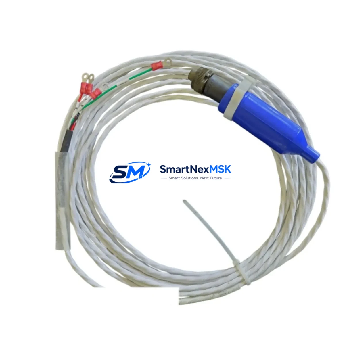
Bently Nevada 130539-17 Retrofit-Ready Proximity Probe Cable for 3300/7200 Series Control Systems
The Bently Nevada 130539-17 is a precision-engineered proximity probe interconnect cable designed for seamless integration into legacy and active vibration monitoring systems built on the Bently Nevada 3300 Series and 7200 Series platforms. As original OEM cables age, become discontinued, or are no longer available through standard distribution channels, the 130539-17 serves as a verified retrofit-ready replacement that preserves signal integrity, maintains system calibration, and eliminates the need for costly full-system overhauls.
For maintenance engineers and reliability teams managing aging turbomachinery protection systems, the 130539-17 is a critical link between the proximity probe tip and the Proximitor® sensor. Its shielded coaxial construction ensures low-noise signal transmission across the full operating range, making it suitable for high-speed rotating equipment including steam turbines, gas compressors, centrifugal pumps, and gearboxes where shaft displacement and vibration data are mission-critical.
Upgrade Compatibility Table
| Parameter | Details |
|---|---|
| SKU / Part Number | 130539-17 |
| Compatible Series | Bently Nevada 3300 Series, 7200 Series |
| Cable Type | Proximity Probe Interconnect (Extension) Cable |
| Connector Interface | Standard Bently Nevada coaxial connector, compatible with 3300 XL 8mm and 11mm probe assemblies |
| Installation Requirement | No hardware modification required; direct plug-in replacement |
| Communication Compatibility | Passive analog signal cable; compatible with all 3300/7200 Series Proximitor® sensor outputs |
| Replacement Recommendation | Replaces aged or discontinued OEM 130539-xx series cables; verify cable length suffix before ordering |
| Commissioning Notes | Re-verify gap voltage after installation; confirm scale factor alignment with monitor card |
| Warranty | 12-Month Warranty included |
Retrofit Planning for Existing Automation Systems
When planning a retrofit or partial upgrade of a Bently Nevada-based machinery protection system, the 130539-17 cable is typically one of the first components to be evaluated. In a standard 3300 Series rack installation, the cable connects the field-mounted proximity probe to the Proximitor® sensor mounted at the junction box or directly on the monitor rack. During a control cabinet upgrade, engineers must account for cable routing paths, conduit fill ratios, and the physical distance between the probe tip and the Proximitor® sensor — all of which determine the correct cable length suffix (e.g., -17 indicating a specific length variant).
In systems where the 3300 Series rack is being migrated to a newer Bently Nevada System 1 platform or a third-party vibration monitor, the 130539-17 cable can often be retained as-is, provided the Proximitor® sensor output voltage and scale factor remain compatible with the new monitor input card. Engineers should cross-reference the existing 3300 RAM (Rack Architecture Module) configuration and confirm that the new monitor card — such as a 3500/42M Proximitor®/Seismic Monitor — accepts the same -18 Vdc bias supply and 200 mV/mil scale factor standard to the 7200 Series probe system.
For sites performing I/O expansion or adding new measurement points to an existing 3500 Series rack, the 130539-17 cable pairs directly with 3300 XL 8mm or 11mm proximity probe assemblies and their corresponding Proximitor® sensors. When integrating additional channels, verify that the 3500 rack has available I/O slots and that the TDI (Transducer Drive Interface) module is configured to support the additional probe circuits. The 3500/20 Rack Interface Module and 3500/22M Transient Data Interface are commonly involved in such expansions and should be confirmed as part of the retrofit BOM.
Communication protocol migration is another key consideration. In older DCS-integrated systems where the 3300 Series rack communicated via Modbus RTU to a DCS such as a Honeywell TDC 3000 or Foxboro I/A Series controller, upgrading to a 3500 Series rack with Ethernet/IP or Modbus TCP capability requires reconfiguring the communication gateway and updating HMI faceplates accordingly. The 130539-17 cable itself is protocol-agnostic, but its replacement is often the trigger event that initiates a broader system review including the 3500/92 Communication Gateway Module and associated network switch infrastructure.
Downtime Control During System Migration
Minimizing unplanned downtime is the primary concern when replacing proximity probe cables on operating machinery. The recommended approach is to perform cable replacement during a scheduled maintenance window, with the machine at rest and the protection system bypassed under a formal Management of Change (MOC) procedure. Before disconnecting the existing 130539-17 or equivalent cable, document the current gap voltage reading at the Proximitor® sensor output — typically between -10 Vdc and -18 Vdc depending on probe gap — and record this as the baseline for post-installation verification.
After installing the new 130539-17 cable, reconnect the Proximitor® sensor and re-energize the probe circuit. Measure the output voltage and compare it against the documented baseline. A deviation of more than ±0.5 Vdc from the original reading may indicate an incorrect probe gap, a damaged probe tip, or a cable impedance mismatch. Adjust the probe gap using the appropriate gap-setting tool until the output voltage returns to the baseline value. Once gap voltage is confirmed, verify the vibration reading on the 3300 or 3500 Series monitor card and confirm that the channel is within the OK relay threshold before removing the bypass.
For systems with redundant probe configurations — common on critical turbomachinery where two probes are mounted 90° apart for XY vibration measurement — replace one cable at a time to maintain continuous monitoring on the redundant channel. This approach preserves the protection system’s ability to detect shaft displacement events throughout the maintenance procedure and eliminates the risk of a full protection system blackout during cable replacement.
Retrofit Support FAQ
Q: Is the 130539-17 a direct drop-in replacement for other 130539-xx cable variants?
A: The 130539 series cables share the same connector interface and electrical characteristics, but differ in cable length. The -17 suffix denotes a specific length. Always verify the required cable length for your installation before ordering to ensure the Proximitor® sensor can be mounted at the correct distance from the probe tip.
Q: What commissioning steps are required after installing the 130539-17?
A: After installation, measure the Proximitor® sensor output voltage to confirm the probe gap is within specification. Verify the vibration reading on the monitor card, confirm the OK relay is energized, and check that the channel alarm setpoints are active. For 3500 Series systems, use the 3500 Rack Configuration Software to confirm channel status before returning the system to service.
Q: Can the 130539-17 be used with non-Bently Nevada vibration monitors?
A: The 130539-17 is a passive coaxial cable and is electrically compatible with any vibration monitor that accepts a standard Proximitor® sensor signal (-18 Vdc bias, 200 mV/mil scale factor). Compatibility with third-party monitors should be confirmed against the monitor’s input specification sheet before installation.
Q: What does the 12-month warranty cover?
A: The 12-month warranty covers manufacturing defects in materials and workmanship under normal operating conditions. It does not cover damage resulting from improper installation, mechanical abuse, or operation outside the specified environmental ratings. Warranty claims are processed through SMARTNEXMSK with a typical turnaround of 5–10 business days.
—
© 2026 SMARTNEXMSK. All rights reserved.
Original Source: https://smartnexmsk.com
Contact: [email protected] | +86 18259474341



