
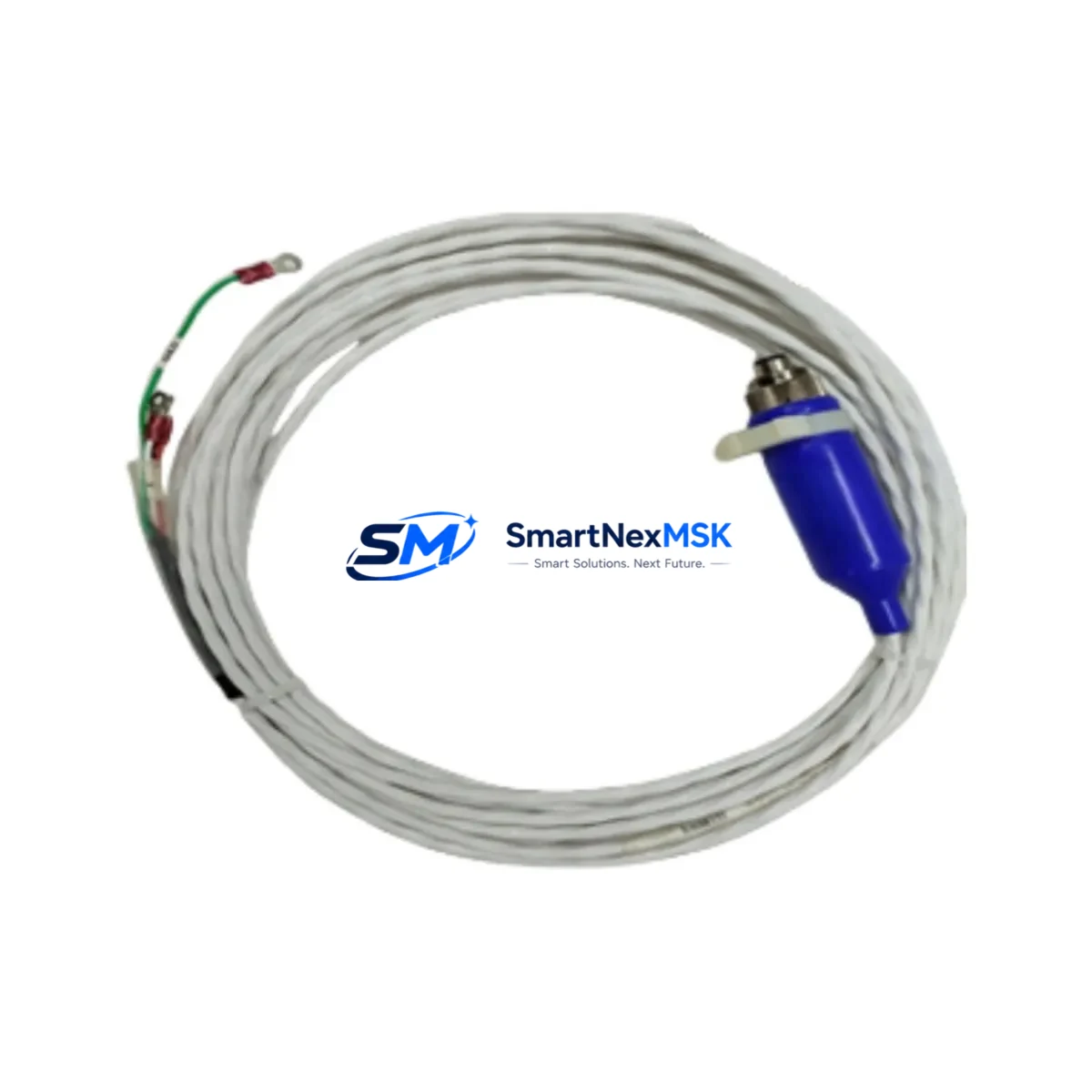
Bently Nevada 130539-30 Spare for 3300 Automation: Spare Replacement & Industrial Downtime Risk Control
The Bently Nevada 130539-30 is an original proximity transducer interconnect cable engineered for the 3300 Series vibration monitoring system — one of the most widely deployed machinery protection platforms in rotating equipment facilities worldwide. Whether you are managing a planned turnaround, responding to an unplanned trip, or building a critical-spares inventory for a gas turbine, compressor, or pump train, the 130539-30 is a front-line component that directly affects signal integrity between the proximity probe and the 3300 Series monitor.
This listing provides a factory-original, pre-shipment tested 130539-30 interconnect cable with a 12-month warranty, available for fast worldwide dispatch. Each unit is inspected for connector integrity, cable shielding continuity, and impedance compliance before shipment — ensuring it arrives ready for immediate installation without additional bench testing.
Spare Maintenance Table
| Parameter | Specification / Detail |
|---|---|
| Part Number / SKU | 130539-30 |
| Brand | Bently Nevada |
| Series Compatibility | Bently Nevada 3300 Series Vibration Monitoring System |
| Product Type | Proximity Transducer Interconnect Cable |
| Cable Length | 30 ft (9.14 m) — suffix “-30” denotes 30-foot cable |
| Connector Type | MIL-spec coaxial, compatible with 3300 XL 8mm / 11mm proximity probe systems |
| Signal Type | Eddy-current proximity signal (DC voltage, –24 VDC bias) |
| Shielding | Double-shielded coaxial construction for EMI/RFI rejection in industrial environments |
| Operating Temperature | –40°C to +121°C |
| Application Environment | Turbines, compressors, pumps, gearboxes — rotating machinery protection |
| Origin | USA (Bently Nevada / Baker Hughes) |
| Installation | Direct replacement; no re-calibration required when replacing same-length cable |
| Maintenance Recommendation | Replace during planned outage or immediately upon signal drift / open-circuit alarm |
| Warranty | 12 Months — covers manufacturing defects and signal performance |
| Pre-Shipment Test | Continuity, shielding integrity, and connector seating verified before dispatch |
Maintenance Planning for Continuous Operation
When a 130539-30 interconnect cable is flagged during routine inspection or triggers a 3300 Series monitor alarm, experienced maintenance engineers know that the cable is rarely the only component that warrants attention. A thorough site assessment should include the following associated components to prevent repeat failures and maximize uptime between outages.
Start at the probe end: the Bently Nevada 330101 or 330103 proximity probe (8mm or 11mm tip) should be inspected for tip damage, thread condition, and gap voltage. If the probe has been in service for more than three years in a high-temperature or high-vibration zone, proactive replacement alongside the 130539-30 cable is standard practice. The 330130 extension cable — the segment running from the probe to the junction box — should also be checked for jacket abrasion, connector corrosion, and continuity, as it operates in the harshest part of the signal path.
At the monitor end, verify the 3300/16 or 3300/20 proximitor / oscillator-demodulator output voltage is within the –10 VDC to –18 VDC nominal range at the correct gap. A drifting proximitor is a common root cause of false alarms that are incorrectly attributed to cable degradation. The 3300 Series rack power supply module should be load-tested; a sagging –24 VDC rail will cause system-wide gap voltage errors across all channels simultaneously.
Inside the control cabinet, inspect the 3300 Series I/O terminal blocks and field wiring barriers for loose terminations, oxidation, and insulation breakdown. Signal integrity issues in proximity systems are frequently traced to high-resistance terminations rather than cable faults. If the installation uses Bently Nevada 3500 Series monitors in the same rack (common in hybrid upgrade scenarios), verify that the 3500/42M or 3500/45 position monitor cards are not sharing a degraded backplane power bus with the 3300 modules.
For facilities running GE Mark VI or Emerson Ovation DCS platforms that receive vibration trip signals from the 3300 system, confirm that the hardwired relay outputs from the 3300 Series relay module are correctly mapped and that the DCS I/O card input thresholds have not drifted. A complete loop check — from probe gap through interconnect cable, proximitor, monitor card, relay output, and DCS input — is the only reliable method to confirm system readiness after a cable replacement.
Finally, review the junction box terminal strip condition and any signal isolators or barriers installed in the loop for intrinsically safe (IS) zone compliance. In hazardous-area installations, a degraded Zener barrier or galvanic isolator can introduce loop resistance that mimics a cable fault, leading to unnecessary cable replacements.
Site Replacement Workflow
Step 1 — Verify compatibility: Confirm the replacement 130539-30 matches the installed cable length (30 ft). Substituting a different suffix (e.g., -25 or -50) will shift the gap voltage calibration and require re-gapping the probe. The 130539-30 is a direct, same-length replacement that maintains the original system calibration.
Step 2 — Isolate and de-energize: Follow site LOTO procedures. The 3300 Series monitor can remain powered during cable swap in non-trip-critical monitoring applications, but consult your site safety plan. For machinery protection applications, coordinate with operations to confirm the machine is offline or in a safe state.
Step 3 — Disconnect and inspect connectors: Remove the existing cable at both the probe/extension cable junction and the proximitor input. Inspect the mating connectors for bent pins, corrosion, or thread damage. Clean with contact cleaner if necessary before installing the new 130539-30.
Step 4 — Install and route: Route the new cable following the original cable path. Avoid sharp bends below the minimum bend radius and ensure the cable is not routed near high-voltage conductors or heat sources. Secure with cable ties at the original support points.
Step 5 — Verify gap voltage: After connection, measure the proximitor output voltage. For a standard 8mm probe at 1.0 mm gap, the nominal output is approximately –10.4 VDC. Confirm the reading is within the system’s configured OK range on the 3300 monitor display.
Step 6 — Clear alarms and return to service: Reset any latched alarms on the 3300 monitor, confirm the channel is in the OK state, and document the replacement in the maintenance management system (CMMS) with the new cable serial number and installation date.
This workflow minimizes downtime to under 30 minutes for a trained technician and eliminates the need for system recalibration when the correct-length 130539-30 is used as a direct replacement.
Spare Parts Support FAQ
Q1: Is the 130539-30 still available as a new original part, or is it only available as surplus?
The 130539-30 is available as a new original Bently Nevada component. Each unit supplied through SMARTNEXMSK is sourced from authorized distribution channels or factory-new stock, not refurbished or repaired surplus. The 12-month warranty applies to new original units only.
Q2: How do I verify compatibility with my existing 3300 Series installation before ordering?
Compatibility is confirmed by matching three parameters: (1) the cable length suffix — “-30” indicates 30 feet; (2) the connector type at the probe/extension cable junction, which must match your installed 8mm or 11mm proximity probe system; and (3) the proximitor model in your rack. If you can provide your proximitor part number and probe model, our technical team can confirm compatibility before shipment.
Q3: What pre-shipment testing is performed on each 130539-30 unit?
Every 130539-30 shipped by SMARTNEXMSK undergoes a three-point inspection: (1) DC continuity check on the center conductor and shield; (2) connector seating and thread integrity verification; and (3) visual inspection of the cable jacket for cuts, kinks, or abrasion. A test report is available upon request for critical-spares procurement documentation.
Q4: What is the recommended spare parts stocking strategy for the 130539-30?
For facilities with four or more 3300 Series channels monitoring critical rotating equipment, a minimum of two 130539-30 cables per cable-length variant in active use is recommended. Interconnect cables are a high-wear consumable in high-vibration environments and should be included in every annual turnaround spare parts kit. Long-term supply agreements are available for facilities requiring guaranteed stock allocation across multiple planned outage cycles.
© 2026 SMARTNEXMSK. All rights reserved.
Original Source: https://smartnexmsk.com
Contact: [email protected] | +86 18259474341



