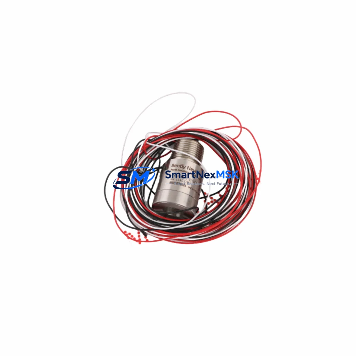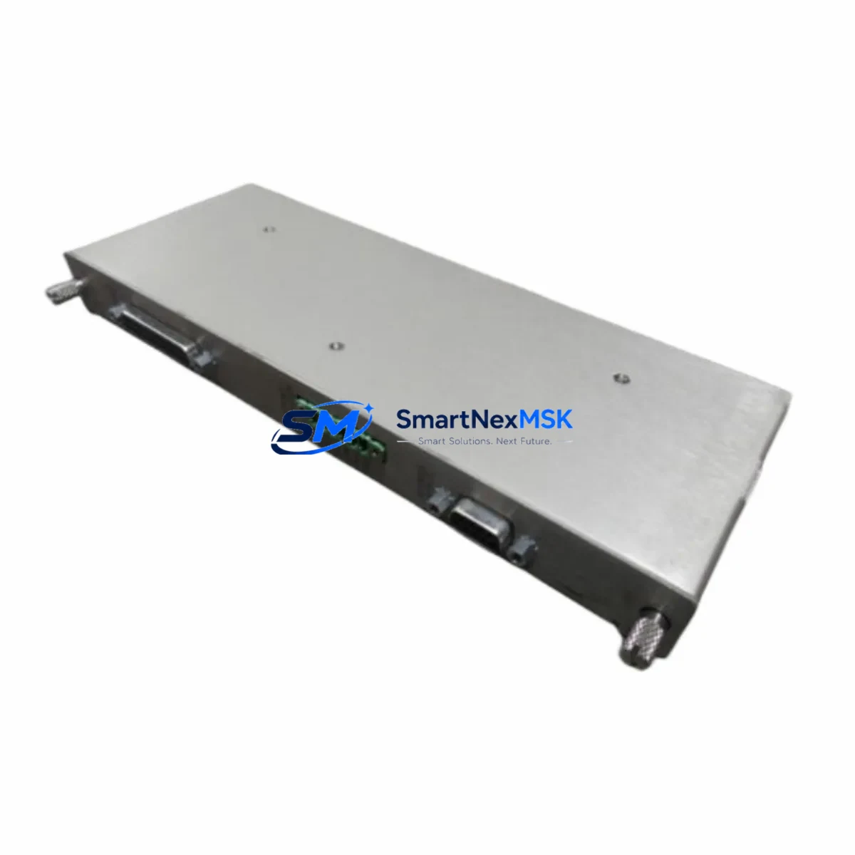
Bently Nevada 133434-01 Maintenance-Ready Spare for 3500 Automation
The Bently Nevada 133434-01 is a Tachometer I/O Module designed for the 3500 Series Machinery Protection System — one of the most widely deployed continuous machinery monitoring platforms in rotating equipment facilities worldwide. Whether you are managing a planned turnaround, responding to an unplanned trip, or building a strategic spare parts inventory for a critical compressor train or turbine skid, the 133434-01 is a high-priority line item that directly affects your system’s ability to monitor shaft speed, overspeed events, and phase reference signals in real time.
Sourced as an original spare, each 133434-01 unit undergoes pre-shipment functional verification to confirm signal integrity, channel isolation, and module communication with the 3500 rack backplane. Maintenance engineers and procurement teams can rely on consistent lead times, documented traceability, and a 12-month warranty covering manufacturing defects and functional failure under normal operating conditions. Global logistics support ensures rapid delivery to refineries, petrochemical plants, LNG terminals, power generation facilities, and offshore platforms.
Spare Maintenance Table
| Parameter | Specification / Detail |
|---|---|
| Part Number / SKU | 133434-01 |
| Brand | Bently Nevada |
| Series | 3500 Machinery Protection System |
| Module Type | Tachometer I/O Module |
| Function | Shaft speed monitoring, overspeed detection, phase reference input |
| Input Channels | 2 Tachometer inputs (proximity probe or magnetic pickup compatible) |
| Rack Compatibility | 3500/20 Rack, 3500/22M Rack (standard and TMR configurations) |
| Communication | 3500 backplane bus; compatible with 3500/92 Communication Gateway |
| Power Supply | Supplied via 3500 rack; compatible with 3500/15 Power Supply Module |
| Operating Temperature | 0°C to 65°C (standard industrial enclosure) |
| Mounting | Direct rack slot insertion, no external wiring adapter required |
| Origin | United States |
| Condition | Original spare, pre-shipment tested |
| Warranty | 12 Months — covers manufacturing defects and functional failure |
| Shipping | Global express; ESD-safe packaging with anti-static shielding |
| Maintenance Recommendation | Replace on alarm escalation, channel fault, or during scheduled turnaround |
Maintenance Planning for Continuous Operation
When a 133434-01 Tachometer I/O Module is flagged for replacement — whether due to a channel fault alarm, a failed self-test, or a scheduled preventive maintenance interval — experienced maintenance engineers know that the module itself is rarely the only component requiring attention. A thorough inspection of the surrounding system is essential to prevent repeat failures and ensure the machinery protection system returns to full operational status.
Begin with the 3500/15 Power Supply Module: verify output voltage stability and check for ripple or transient events that may have stressed the tachometer module’s internal circuitry. A degraded power supply is a common root cause of intermittent I/O module faults in long-running 3500 racks. Next, inspect the 3500/20 Rack backplane connectors for oxidation, bent pins, or contamination — poor backplane contact can cause false channel faults that are misdiagnosed as module failure.
Review the proximity probe cables and extension cables connected to the tachometer inputs. Damaged cable jackets, connector corrosion, or incorrect cable lengths can introduce signal noise that triggers nuisance alarms or degrades speed measurement accuracy. If the installation uses magnetic pickup sensors instead of proximity probes, inspect the sensor gap, mounting torque, and cable shielding continuity. The 3500/50 Tachometer Monitor, if installed in the same rack, should also be checked for configuration consistency with the 133434-01 I/O module parameters.
For systems integrated with a DCS or safety instrumented system, verify the 3500/92 Communication Gateway Module is correctly mapped and that Modbus or OPC data tags for speed channels are updating normally after module replacement. If the rack includes a 3500/32 4-Channel Relay Module, confirm that overspeed trip relay setpoints and latching logic are intact and have not been inadvertently reset during the maintenance window. Terminal blocks and field wiring terminations at the I/O module’s rear connector should be re-torqued to specification and inspected for insulation breakdown.
Procurement engineers building a strategic spare parts kit for a 3500-based machinery protection system should consider stocking the 3500/22M Rack as a complete chassis spare for critical applications, alongside individual module spares such as the 3500/40M Proximitor/Seismic Monitor and the 3500/42M Proximitor/Seismic Monitor for radial vibration channels. A well-structured spare parts inventory aligned to your site’s machinery criticality matrix significantly reduces mean time to repair (MTTR) and supports compliance with API 670 machinery protection requirements.
Site Replacement Workflow
Replacing the 133434-01 in a live 3500 rack follows a structured sequence to minimize downtime and avoid inadvertent process trips. Before beginning, confirm with the control room that the affected machinery channel is in bypass or that the process unit is in a safe state for maintenance. Document the existing module configuration using the System 1 software or the rack’s local display — record channel setpoints, full-scale ranges, and alarm/trip thresholds so they can be verified after the new module is installed.
Power down the rack slot if the system supports hot-swap isolation, or coordinate a controlled rack power-down for non-hot-swap configurations. Remove the faulty 133434-01 by releasing the front panel latch and sliding the module out of the rack slot. Inspect the rear connector on both the module and the backplane for damage before inserting the replacement unit. Seat the new 133434-01 firmly until the latch engages, then restore power and allow the module to complete its self-test sequence.
Using System 1 or the rack configuration software, reload the saved channel configuration and verify that speed readings are within expected range for the current operating condition. Confirm that all alarm and trip setpoints are correctly restored and that the communication gateway is reporting the channel as healthy. Remove the bypass and return the machinery protection channel to normal monitoring status. Log the replacement in your CMMS with the new module’s serial number and the date of installation to support warranty tracking and future maintenance planning.
This workflow applies equally to planned turnaround replacements and emergency unplanned outages. Having a pre-tested 133434-01 spare on the shelf — rather than waiting for procurement after a failure — is the single most effective way to reduce unplanned downtime on rotating equipment protected by the 3500 system.
Spare Parts Support FAQ
Q1: Is the 133434-01 compatible with both standard and TMR (Triple Modular Redundant) 3500 rack configurations?
The 133434-01 Tachometer I/O Module is designed for use in standard 3500 rack configurations. For TMR applications using the 3500/22M rack, compatibility should be verified against the specific rack revision and firmware version. Contact our technical team with your rack model and firmware details for confirmation before ordering for TMR installations.
Q2: What pre-shipment testing is performed on the 133434-01 before delivery?
Each unit undergoes functional verification including power-on self-test confirmation, channel input signal integrity check, and backplane communication validation. Units are shipped in ESD-safe anti-static packaging with individual identification labels. A 12-month warranty covering manufacturing defects and functional failure under normal operating conditions is included with every shipment.
Q3: How should the 133434-01 be stored as a long-term spare?
Store the module in its original ESD-safe packaging in a climate-controlled environment with temperature between 0°C and 70°C and relative humidity below 85% non-condensing. Avoid storage near strong electromagnetic fields or corrosive atmospheres. Inspect the module annually and perform a power-on self-test before deploying a long-term stored spare to confirm functionality prior to installation.
Q4: Can the 133434-01 replace older or discontinued Bently Nevada tachometer module variants?
The 133434-01 is the current production spare for its slot position in the 3500 system. Compatibility with earlier tachometer module variants depends on rack revision, backplane version, and firmware. Our team can cross-reference your existing module part number against the 133434-01 specification to confirm drop-in compatibility or identify any configuration adjustments required before installation.
© 2026 SMARTNEXMSK. All rights reserved.
Original Source: https://smartnexmsk.com
Contact: [email protected] | +86 18259474341