
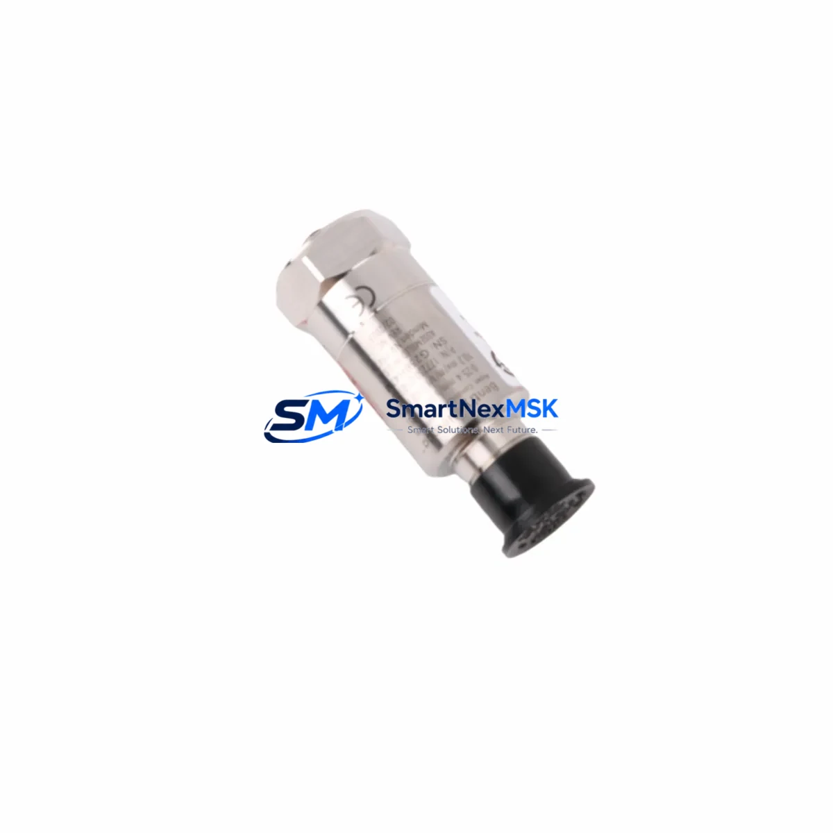
Bently Nevada 177230-01-01-05 Retrofit-Ready Seismic Velocity Transmitter for 177230 Series Control Systems
The Bently Nevada 177230-01-01-05 is a seismic velocity transmitter engineered for seamless integration into legacy vibration monitoring and machinery protection systems built around the Bently Nevada 177230 Series platform. As original equipment reaches end-of-life or becomes increasingly difficult to source, the 177230-01-01-05 serves as a verified retrofit-ready replacement that preserves existing wiring infrastructure, signal conditioning architecture, and 4–20mA output compatibility — minimizing engineering rework and reducing total migration cost.
This module is widely deployed in turbine protection panels, compressor monitoring racks, and rotating machinery control cabinets where continuous vibration data is critical to plant safety and uptime. Its robust housing and field-proven signal path make it a preferred choice for maintenance engineers executing planned upgrades or emergency replacements on aging Bently Nevada installations.
When integrating the 177230-01-01-05 into an existing system, engineers should verify power supply capacity — typically 18–30 VDC — against the existing rail shared with adjacent modules such as the Bently Nevada 3500/42M Proximitor/Seismic Monitor or the 3500/40M Proximitor Monitor. Terminal block wiring should be confirmed against the original loop drawing, paying particular attention to shield grounding and signal return paths to avoid ground loop interference that can corrupt vibration readings.
Backplane and rack compatibility is a key consideration during retrofit planning. The 177230-01-01-05 is designed for use within standard Bently Nevada rack assemblies. If the existing rack is a legacy 3300 Series or early 3500 Series chassis, confirm slot addressing and module addressing jumper settings before installation. Mismatched module addresses will prevent the system from recognizing the new transmitter and may trigger false alarms on the Bently Nevada 3500 Rack Interface Module (RIM).
Program compatibility should be reviewed at the DCS or PLC level. Plants running Emerson Ovation DCS or Honeywell Experion PKS with hardwired vibration inputs will typically require no software changes if the 4–20mA signal range and tag scaling remain unchanged. However, if the replacement is part of a broader migration from hardwired I/O to a Profibus DP or FOUNDATION Fieldbus communication architecture, additional configuration in the field device integration (FDI) layer will be required. In such cases, coordinate with the HMI engineering team to update faceplate displays and alarm setpoints in the operator workstation.
For plants using Rockwell Automation ControlLogix or CompactLogix PLCs as the primary control platform, the 177230-01-01-05 analog output connects to standard analog input modules such as the 1756-IF16 or 1769-IF4 cards. Verify the input channel scaling in Studio 5000 Logix Designer matches the transmitter’s output range to ensure accurate engineering unit conversion on the HMI display.
Upgrade Compatibility Table
| Parameter | Details |
|---|---|
| Compatible Series | Bently Nevada 177230 Series, 3300 Series, 3500 Series |
| Output Signal | 4–20mA analog, compatible with standard PLC/DCS analog input cards |
| Power Supply | 18–30 VDC (verify against existing rail capacity) |
| Terminal Wiring | Retain existing loop wiring; confirm shield grounding per original drawing |
| Backplane / Rack | Standard Bently Nevada rack; verify slot address jumpers |
| Communication Compatibility | Hardwired 4–20mA; Profibus DP / FOUNDATION Fieldbus migration requires additional FDI configuration |
| Replacement Recommendation | Direct drop-in for 177230-01-01-05; cross-reference 177230-01-01-01 and 177230-01-01-03 variants for alternate configurations |
| Commissioning Notes | Verify module address, confirm HMI tag scaling, test alarm setpoints before returning to service |
| Warranty | 12-Month Warranty — covers manufacturing defects and functional failure under normal operating conditions |
Retrofit Planning for Existing Automation Systems
A successful retrofit of the 177230-01-01-05 into an operational plant environment requires a structured pre-installation review. Begin by auditing the existing control cabinet layout to identify all modules sharing the same rack or power bus. Common co-installed components include the Bently Nevada 3500/15 Power Supply Module, the 3500/20 Rack Interface Module, and proximity probe driver cards such as the 3500/25 Enhanced Keyphasor Module. Each of these modules draws from the same backplane power budget, and adding or replacing a transmitter module may require a power margin calculation to confirm the supply is not overloaded.
Terminal block wiring should be documented before removal of the legacy module. Photograph or sketch the existing wiring, noting wire color, terminal number, and shield connection point. The 177230-01-01-05 uses a standard two-wire 4–20mA loop configuration, but some legacy installations may have three-wire or sourcing configurations that require a wiring adapter or loop isolator such as a Phoenix Contact MACX MCR-SL-CAC-5-I-OLP signal conditioner to maintain signal integrity during the transition.
If the retrofit is part of a broader I/O expansion project — for example, adding new measurement points to an existing Bently Nevada 3500 Series rack — consider whether the rack has available slots for additional modules such as the 3500/42M Proximitor/Seismic Monitor or the 3500/45 Position Monitor. Planning I/O expansion at the same time as a module replacement reduces future downtime and avoids repeat cabinet outages.
For plants migrating from legacy Bently Nevada systems to modern DCS platforms, the 177230-01-01-05 can serve as an interim solution that maintains vibration monitoring continuity while the broader migration to a Emerson AMS Device Manager or OSIsoft PI data historian integration is completed. This staged approach allows engineering teams to validate new data paths without disrupting existing protection logic.
Programming cable access is another practical consideration. If the replacement requires re-addressing or reconfiguring the module via a Bently Nevada 3500 Configuration Software session, ensure the RS-232 or USB-to-serial programming cable and a compatible laptop with the configuration utility are available on-site before the maintenance window begins.
Downtime Control During System Migration
Minimizing unplanned downtime during a module replacement is the primary operational concern for any maintenance team. For the 177230-01-01-05, the recommended approach is to pre-configure and bench-test the replacement module before the scheduled maintenance window. This includes verifying the output signal at 4mA (0% of range) and 20mA (100% of range) using a calibrated loop calibrator, and confirming the module powers up correctly on a bench power supply before installation in the live rack.
During the maintenance window, place the affected vibration channel in bypass or maintenance mode at the DCS or safety system level to prevent spurious trips while the module is disconnected. Document the bypass action in the plant’s management of change (MOC) system and notify the control room operator before proceeding. Once the 177230-01-01-05 is installed and wired, restore the channel from bypass only after confirming the live signal reads within the expected range on the operator workstation HMI.
Original program logic — including alarm setpoints, trip thresholds, and signal scaling — should be preserved without modification unless the replacement is part of a deliberate setpoint review. Retain a backup of the existing DCS or PLC configuration before making any changes. For Rockwell Automation systems, export the Studio 5000 project file; for Emerson DeltaV or Ovation systems, use the built-in configuration backup utility. This ensures rapid recovery if the new module exhibits unexpected behavior during initial commissioning.
Field commissioning should include a functional test of the full signal chain: from the seismic sensor through the 177230-01-01-05 transmitter, through the analog input card, to the HMI display and historian. Confirm that the vibration reading tracks correctly as the machine is brought back online, and verify that all associated alarms and trips activate at the correct setpoints before releasing the equipment to normal operation.
Retrofit Support FAQ
Q: Is the 177230-01-01-05 a direct drop-in replacement for other 177230 Series variants?
A: The 177230-01-01-05 is the primary variant in the 177230 Series and is compatible with standard 177230 Series rack and wiring configurations. Cross-reference with variants such as 177230-01-01-01 and 177230-01-01-03 to confirm output range and connector type before installation. Contact our technical team if you need a cross-reference confirmation for your specific application.
Q: What commissioning steps are required after installation?
A: After physical installation, verify module address settings, confirm the 4–20mA output reads correctly at the DCS or PLC analog input card, update HMI tag scaling if required, and test all associated alarm and trip setpoints. A full loop calibration check using a certified loop calibrator is recommended before returning the channel to service.
Q: How do I confirm wiring compatibility with my existing terminal block layout?
A: The 177230-01-01-05 uses a standard two-wire 4–20mA loop configuration. Compare the terminal block pinout in the module datasheet against your existing loop drawing. If your installation uses a three-wire or sourcing configuration, a loop isolator or signal conditioner may be required. Our team can provide wiring guidance based on your specific cabinet layout.
Q: What does the 12-month warranty cover?
A: The 12-month warranty covers manufacturing defects and functional failure under normal operating conditions from the date of shipment. Each unit undergoes pre-shipment functional testing to verify output signal accuracy and power-up behavior. Warranty claims are supported by our technical team with replacement or repair turnaround coordinated to minimize your system downtime.
© 2026 SMARTNEXMSK. All rights reserved.
Original Source: https://smartnexmsk.com
Contact: [email protected] | +86 18259474341



