
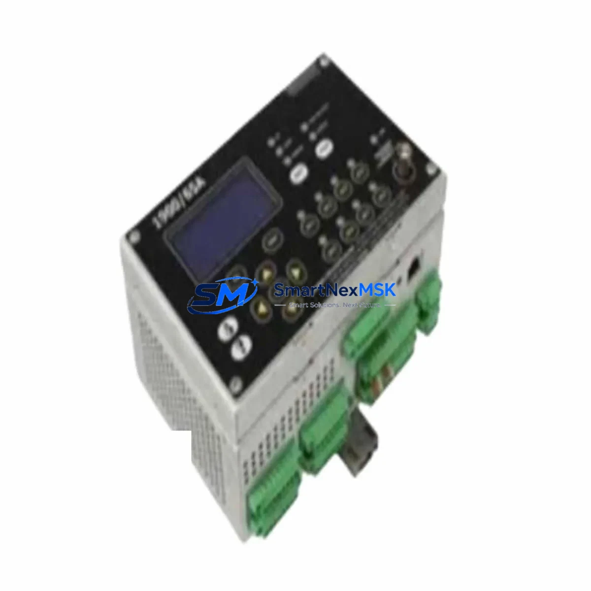
Bently Nevada 1900/65A 172323-01 Retrofit-Ready Vibration Monitor for 1900 Series Control Systems
The Bently Nevada 1900/65A (Part No. 172323-01 / alternate 167699-02) is a dual-channel, rack-mounted vibration monitoring module engineered for continuous machinery protection in rotating equipment applications. As legacy 3300 Series and early 1900 Series installations reach end-of-service life, the 1900/65A has become the preferred drop-in upgrade path for plants seeking to modernize their condition monitoring infrastructure without a full system overhaul. This module is stocked, tested, and shipped with a 12-month warranty from SMARTNEXMSK.
Upgrade Compatibility Table
| Parameter | Details |
|---|---|
| SKU / Part Number | 1900/65A — 172323-01 (alt: 167699-02) |
| Series Compatibility | Bently Nevada 1900 Series rack system |
| Common Replaced Models | 3300/16, 3300/20, 3300/55, 1900/65 (earlier revisions) |
| Channels | Dual-channel vibration input |
| Rack / Backplane Interface | 1900 Series 19-inch rack, standard backplane connector |
| Communication Compatibility | Modbus RTU / RS-485; System 1 software compatible |
| Power Requirement | 24 VDC via rack power supply (e.g., 1900/10 or 1900/12) |
| Installation Requirement | Slot-specific addressing; verify module address jumpers before insertion |
| Retrofit Recommendation | Direct replacement for 172323-01 / 167699-02; confirm terminal wiring map |
| Commissioning Note | Re-configure alert/danger setpoints in System 1 after swap |
| Warranty | 12 Months — Covered by SMARTNEXMSK |
Retrofit Planning for Existing Automation Systems
Replacing the 1900/65A 172323-01 in an operating plant requires careful pre-outage planning across multiple system layers. Before pulling the old module, engineers should document the existing terminal wiring using the original I/O drawing set — the dual-channel inputs typically connect to Bently Nevada proximity probes (e.g., 330180 or 330130 series) via field junction boxes, and any mismatch in cable shielding or grounding will introduce noise into the vibration signal chain.
The 1900 Series rack uses a passive backplane, so slot assignment directly determines the module’s Modbus node address. Before removal, record the address configuration from the existing 1900/65A and replicate it on the replacement unit using the onboard DIP switches or jumper blocks. If the plant runs Bently Nevada System 1 condition monitoring software, the channel configuration — including full-scale range, transducer type, and alert/danger thresholds — must be re-entered or restored from a saved configuration file after the new module is seated.
Plants migrating from the older 3300 Series (such as the 3300/16 dual-channel monitor or the 3300/55 temperature monitor) to the 1900 platform will need to account for differences in terminal block layout. The 3300 Series used a dedicated I/O termination module, while the 1900/65A integrates termination directly on the front panel — a change that simplifies wiring but requires re-termination of field cables. In these cases, a 1900/01 or 1900/02 I/O module may be required to bridge legacy field wiring to the new rack format.
For sites running Modbus RTU over RS-485, verify that the host DCS or SCADA system (such as a Honeywell DeltaV node, an ABB AC800M controller, or a Rockwell ControlLogix gateway) has the correct register map for the 1900/65A. The register layout differs from the 3300 Series, and the polling interval should be reviewed to avoid communication timeouts during the transition. If the plant uses a 1900/20 communication gateway, confirm firmware compatibility with the replacement module revision.
Power budget verification is essential when adding or replacing modules in an existing 1900 rack. The 1900/10 or 1900/12 power supply module must have sufficient headroom to support the 1900/65A alongside other installed modules such as the 1900/25 keyphasor module or 1900/27 tachometer input module. Overloading the rack power supply is a common cause of intermittent faults after a module swap. A current draw audit of all installed modules should be completed before the outage window begins.
HMI screens tied to the vibration monitoring channels — whether on a local operator panel or a plant-wide SCADA display — should be reviewed and updated to reflect any tag name or address changes introduced by the new module. If the plant uses a Bently Nevada TDXnet or Orbit 60 Series data acquisition system, the channel mapping within the historian must also be updated to prevent data gaps in the vibration trend archive.
Downtime Control During System Migration
Minimizing unplanned downtime during a 1900/65A module replacement begins with a structured pre-outage checklist. The replacement module should be bench-tested and pre-configured — including address settings, channel scaling, and communication parameters — before the maintenance window opens. A pre-configured spare eliminates the most time-consuming steps from the critical path and reduces the risk of configuration errors under time pressure.
Where process conditions allow, consider a “hot-standby” approach: install the new 1900/65A in an adjacent empty slot, configure it fully in System 1, and verify communication with the host system before removing the original module. This approach allows the engineering team to validate the replacement without interrupting the live monitoring channel. Once the new module is confirmed operational, the field wiring can be transferred during a brief, controlled outage.
For plants where continuous monitoring is mandatory (e.g., turbine protection systems), coordinate the swap with the control room to place the affected machine in a manually supervised state during the transition. Ensure that the danger bypass function is activated in System 1 for the affected channels before the module is removed, and that it is deactivated and all setpoints are re-verified before returning the machine to automatic protection. Document the as-found and as-left setpoint values for the maintenance record.
After reinsertion, allow the 1900/65A a full warm-up period (typically 15–30 minutes) before accepting vibration readings as valid for protection purposes. Verify that the OK relay output is energized and that System 1 shows the channel in a healthy, non-alarmed state before releasing the machine to operations.
Retrofit Support FAQ
Q1: Is the 172323-01 a direct drop-in replacement for the 167699-02?
Yes. Both part numbers refer to the same 1900/65A dual-channel vibration monitor at different revision or ordering configurations. They share the same backplane connector, terminal layout, and System 1 configuration interface. No hardware modification is required for substitution.
Q2: What wiring changes are needed when replacing a 3300 Series monitor with the 1900/65A?
The 3300 Series uses a separate I/O termination module, while the 1900/65A has integrated front-panel terminals. Field cables from the proximity probes must be re-terminated to the 1900/65A terminal block. Verify shield grounding continuity and confirm that cable lengths remain within the transducer manufacturer’s specification. A wiring diagram comparison between the 3300 and 1900 terminal assignments is strongly recommended before the outage.
Q3: How is the module address configured, and does it affect the Modbus register map?
The module address is set via onboard jumpers or DIP switches and must match the slot assignment defined in the System 1 configuration. The Modbus register base address is derived from the module address, so any change in slot position will shift the register map. Update the host DCS or SCADA polling configuration accordingly to avoid communication faults after the swap.
Q4: What does the 12-month warranty cover, and what is the process for a warranty claim?
The 12-month warranty covers manufacturing defects and functional failures under normal operating conditions. Each unit shipped by SMARTNEXMSK undergoes pre-shipment functional testing. In the event of a warranty claim, contact [email protected] with the order reference and a description of the fault. SMARTNEXMSK will arrange for inspection and, where applicable, replacement or repair at no additional cost within the warranty period.
© 2026 SMARTNEXMSK. All rights reserved.
Original Source: https://smartnexmsk.com
Contact: [email protected] | +86 18259474341



