
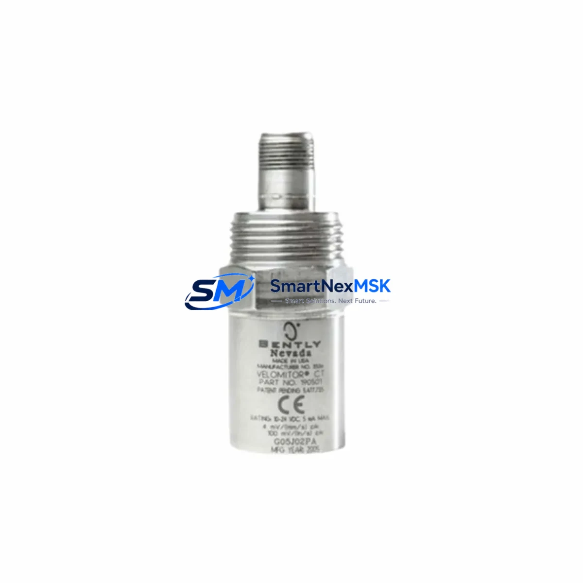
Bently Nevada 190501-01-00-00 Maintenance-Ready Spare Velomitor CT
For maintenance engineers and procurement teams managing rotating machinery protection systems, the Bently Nevada 190501-01-00-00 Velomitor CT seismic velocity transducer is a critical spare that directly supports continuous operation of turbines, compressors, pumps, and motors monitored under the Bently Nevada 3500 Series machinery protection platform. This original-specification spare is held in verified inventory, tested before shipment, and backed by a 12-month warranty — giving maintenance planners the confidence to schedule replacements without unplanned downtime risk.
The Velomitor CT (190501-01-00-00) is a piezo-velocity transducer designed for absolute casing vibration measurement. It outputs a velocity signal (mV/mm/s or mV/in/s) compatible with the Bently Nevada 3500/42M Proximitor/Seismic Monitor module, making it a direct drop-in replacement for aging or failed units in existing control cabinets without requiring firmware changes or recalibration of the monitoring rack.
Spare Maintenance Table
| Parameter | Specification |
|---|---|
| SKU / Part Number | 190501-01-00-00 |
| Product Type | Seismic Velocity Transducer (Velomitor CT) |
| Brand / Series | Bently Nevada / Velomitor CT |
| Output Signal | Velocity (piezo-velocity, mV per mm/s) |
| Compatible Monitor | Bently Nevada 3500/42M Proximitor/Seismic Monitor |
| Mounting | Stud mount, radial or axial casing installation |
| Connector Type | MIL-C-5015 style, 2-pin |
| Operating Temperature | -40°C to +121°C |
| Application Environment | Industrial rotating machinery, turbines, compressors, pumps |
| Replacement Compatibility | Direct replacement for 190501-01-00-00; compatible with 3500 Series racks |
| Calibration Required | No — plug-and-play with existing 3500/42M configuration |
| Pre-shipment Testing | Yes — functional and signal output verified |
| Warranty | 12 Months from date of shipment |
| Lead Time | In stock — ships within 3–5 business days |
Maintenance Planning for Continuous Operation
When a Velomitor CT (190501-01-00-00) is flagged during routine inspection or triggers a high-vibration alarm, the replacement workflow extends beyond the transducer itself. A thorough maintenance plan should include verification of the Bently Nevada 3500/42M Proximitor/Seismic Monitor input channel — confirming that the channel is not in bypass mode and that the OK relay output is functioning correctly before the new transducer is energized.
The signal cable connecting the Velomitor CT to the monitor rack deserves equal attention. The Bently Nevada 330130 series interconnect cable (or equivalent armored coaxial cable) should be inspected for insulation damage, connector corrosion, and continuity. A degraded cable can produce false vibration readings even after a transducer swap, leading to unnecessary repeat maintenance events.
Inside the 3500 Series rack, the 3500/15 Power Supply module should be checked for stable DC output, as voltage fluctuations can affect transducer sensitivity and signal baseline. If the rack houses a 3500/20 Rack Interface Module (RIM), verify that the Modbus or Ethernet communication link to the DCS or SCADA system is intact and that the channel configuration has not been inadvertently altered during any recent firmware update.
For sites running a broader Bently Nevada monitoring suite, the 3500/40M Proximitor/Seismic Monitor (used for eddy-current proximity probes on the same shaft) should be cross-checked alongside the Velomitor CT replacement to ensure that both radial vibration and casing vibration channels are reporting consistent baseline values after the spare is installed. The 3500/25 Keyphasor Module, if present, should also be confirmed operational, as phase reference data is essential for balancing analysis following any vibration-related maintenance event.
Procurement engineers building a spare parts inventory for a turbine or compressor train should consider stocking the Bently Nevada 330180-51-00 extension cable alongside the 190501-01-00-00 transducer, as cable and connector failures account for a significant share of seismic channel faults. Additionally, the 3500/22M Transient Data Interface (TDI) module — used for waveform capture during startup and shutdown — should be included in the annual inspection checklist, as transient data is invaluable for diagnosing the root cause of the vibration event that triggered the transducer replacement.
For control cabinets housing both the 3500 rack and associated relay output panels, inspect the terminal blocks and DIN rail assemblies for loose connections, particularly on the OK relay and danger relay wiring. Loose terminals are a common source of intermittent faults that can be misdiagnosed as transducer failure. A signal isolator or barrier installed between the monitor output and the DCS analog input card should also be tested for correct scaling and loop integrity.
Site Replacement Workflow
Replacing the Bently Nevada 190501-01-00-00 Velomitor CT on a live machine requires a structured approach to minimize downtime and protect the existing program logic and alarm configuration stored in the 3500 rack.
Step 1 — Pre-replacement verification: Confirm the replacement unit’s part number matches 190501-01-00-00 exactly. Check the sensitivity value (mV/mm/s) printed on the transducer label against the channel configuration in the 3500/42M monitor. Mismatched sensitivity values will cause incorrect vibration readings without triggering a hardware fault.
Step 2 — Channel bypass: Place the affected channel in bypass mode via the 3500 rack front panel or the System 1 software interface before disconnecting the old transducer. This prevents a spurious danger alarm from triggering a machine trip during the swap.
Step 3 — Mechanical removal and installation: Remove the old Velomitor CT from its stud mount, clean the mounting surface, and install the replacement unit to the specified torque. Reconnect the signal cable, ensuring the MIL-spec connector is fully seated and the locking ring is secure.
Step 4 — Signal verification: Remove the channel from bypass and observe the live vibration reading. Compare the baseline value against historical trend data from System 1 or the DCS historian. A reading within ±10% of the pre-fault baseline confirms a successful replacement.
Step 5 — Documentation: Record the replacement in the maintenance management system (CMMS), noting the old unit’s serial number, the new unit’s serial number, installation date, and post-replacement baseline reading. This record supports warranty claims and future predictive maintenance scheduling.
Spare Parts Support FAQ
Q1: Is the 190501-01-00-00 a direct drop-in replacement for older Velomitor CT units?
Yes. The 190501-01-00-00 maintains the same mechanical dimensions, connector type, sensitivity specification, and electrical interface as previous Velomitor CT variants. No modifications to the 3500/42M monitor configuration are required for a like-for-like replacement.
Q2: How is the unit tested before shipment?
Each 190501-01-00-00 unit is functionally tested for output signal integrity, sensitivity accuracy, and connector continuity prior to packaging. A test report is available upon request. Units are shipped in anti-static, impact-resistant packaging to prevent transit damage.
Q3: What is covered under the 12-month warranty?
The 12-month warranty covers manufacturing defects, signal output failures, and connector faults under normal operating conditions. It does not cover damage resulting from incorrect installation, overvoltage, or mechanical impact. Warranty claims are processed within 5 business days of receiving the returned unit.
Q4: Can you supply multiple units for a planned outage spare kit?
Yes. We maintain stock of the 190501-01-00-00 and can fulfill multi-unit orders for planned outage spare kits or site-wide inventory programs. Volume pricing and expedited shipping options are available — contact our team for a formal quotation.
© 2026 SMARTNEXMSK. All rights reserved.
Original Source: https://smartnexmsk.com
Contact: [email protected] | +86 18259474341



