
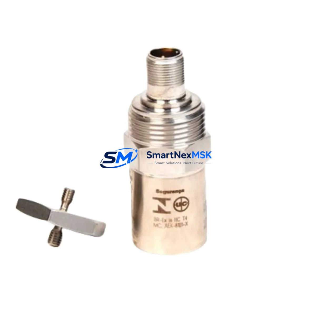
Bently Nevada 190501-01-00-CN Retrofit-Ready Velocity Transducer for 3300 Series Control Systems
The Bently Nevada 190501-01-00-CN is a Velomitor CT piezoelectric velocity transducer engineered for high-reliability vibration monitoring in rotating machinery protection systems. As legacy 3300 Series installations age and original spare inventories diminish, the 190501-01-00-CN has become a critical retrofit component for engineers tasked with sustaining continuous machinery protection without full system replacement. SMARTNEXMSK maintains verified stock of this unit, fully tested and backed by a 12-month warranty, ready for immediate deployment in brownfield modernization projects.
Upgrade Compatibility Table
| Parameter | Details |
|---|---|
| SKU / Part Number | 190501-01-00-CN |
| Brand / OEM | Bently Nevada |
| Compatible Platform | Bently Nevada 3300 Series Machinery Protection System |
| Transducer Type | Velomitor CT Piezoelectric Velocity Transducer |
| Mounting Interface | Standard industrial stud mount; compatible with existing 3300 Series field wiring |
| Signal Output | Velocity (mV/mm/s); direct replacement for legacy Velomitor CT outputs |
| Communication Compatibility | Hardwired analog signal; integrates with 3300/16 and 3300/20 monitor cards |
| Replacement Recommendation | Direct drop-in for discontinued 190501-01-00-CN units; verify cable connector pinout before installation |
| Commissioning Notes | Confirm sensitivity scaling in 3300 Series monitor; re-zero baseline after installation |
| Warranty | 12-Month Warranty — covers manufacturing defects and functional performance |
Retrofit Planning for Existing Automation Systems
Replacing the 190501-01-00-CN in an operating plant requires careful coordination across multiple system layers. Before removing the legacy transducer, engineers should document the existing cable routing, connector type, and field junction box terminations. The Velomitor CT connects to the Bently Nevada 3300/16 Velocity Monitor or the 3300/20 Dual Velocity Monitor via a dedicated coaxial or shielded twisted-pair cable run. Confirm that the existing cable is rated for the signal frequency range of the replacement unit before reuse.
In many 3300 Series installations, the velocity transducer shares a common rack with proximity probe drivers such as the 3300/05 Proximitor Sensor and eddy current displacement transducers. When planning the retrofit, inspect the 3300 XL 8-slot or 16-slot rack for available card slots if the project scope includes adding redundant monitoring channels. The 3300/15 Keyphasor Module, if present, should remain undisturbed during transducer replacement to preserve phase reference signals used by the System 1 Condition Monitoring Software.
Power supply integrity is a prerequisite for any retrofit. Verify that the 3300 Series power supply module — typically a 3300/05 or equivalent — delivers stable ±24 VDC to the monitor cards before and after transducer swap. Voltage sag during the changeover window can trigger nuisance trips or corrupt stored alarm setpoints. Where possible, coordinate with the control room to temporarily mask the affected channel in the DCS or safety instrumented system (SIS) during the physical swap, then restore monitoring before unmasking.
For plants running GE Bently Nevada System 1 software, the transducer channel configuration — including full-scale range, alert setpoints, and danger setpoints — is stored in the software database. After installing the 190501-01-00-CN, re-verify that the channel sensitivity value (mV/mm/s) entered in System 1 matches the transducer’s calibration certificate. A mismatch here will produce incorrect velocity readings and may cause false trips on high-speed rotating equipment such as steam turbines, compressors, or pumps.
Projects that combine transducer replacement with broader control system upgrades may also involve migrating from legacy serial communication links to Ethernet-based protocols. In these cases, the 3500/92 Communication Gateway Module or a third-party OPC-DA/OPC-UA bridge is commonly used to interface the 3300 Series rack with modern DCS platforms from Emerson DeltaV, Honeywell Experion, or ABB 800xA. Confirm that the gateway firmware version supports the monitor card revision installed in the rack.
Where I/O expansion is part of the modernization scope, the 3300 Series rack may be supplemented with additional monitor cards. Ensure that the rack backplane — whether an 8-slot or 16-slot chassis — has sufficient power headroom for the added cards. The 3300/05 power supply module has a defined maximum load; exceeding it will cause intermittent resets. If the backplane is at capacity, a secondary rack with its own power supply and a 3300/93 Data Manager Module for inter-rack communication may be required.
Downtime Control During System Migration
Minimizing unplanned downtime is the primary operational constraint in any machinery protection system retrofit. The 190501-01-00-CN replacement can typically be completed within a planned maintenance window of two to four hours when all materials and documentation are staged in advance. The following sequence is recommended to protect original program logic and maintain field control continuity:
First, export the current channel configuration from System 1 or the 3300 Series monitor front panel before any hardware is disturbed. This configuration backup preserves alert and danger setpoints, time delays, and relay output assignments. Second, coordinate with the operations team to place the affected machinery in a safe, monitored state — ideally at reduced load or on standby — before the transducer is disconnected. Third, perform the physical swap, verify connector seating and cable continuity with a multimeter, and restore power to the monitor card. Fourth, confirm live velocity readings against a portable vibration reference instrument before returning the channel to active protection duty. Fifth, restore all alarm setpoints from the saved configuration and document the as-left condition in the plant maintenance management system (CMMS).
For critical machinery where zero-downtime replacement is required, a temporary bypass relay or a portable vibration monitor can shadow the channel during the swap interval, ensuring that the machinery protection function is never fully interrupted. This approach is particularly important for API 670-compliant installations where continuous monitoring is a contractual or regulatory requirement.
Retrofit Support FAQ
Q1: Is the 190501-01-00-CN a direct replacement for the original Velomitor CT, and will it work with my existing 3300 Series monitor cards?
Yes. The 190501-01-00-CN is the current Bently Nevada part number for the Velomitor CT piezoelectric velocity transducer and is designed as a direct functional replacement for earlier Velomitor CT variants used in 3300 Series installations. Verify the connector type and cable pinout at the field junction box before installation, as some early installations used non-standard connector configurations.
Q2: What wiring checks should I perform before and after installation?
Before removal, measure the existing transducer’s output voltage at the monitor card input terminals with the machine running to establish a baseline. After installing the 190501-01-00-CN, verify cable shield continuity, confirm that the coaxial or shielded cable is properly grounded at one end only (typically at the monitor card end), and check for any ground loops that could introduce noise into the velocity signal. Re-measure the output voltage at the monitor card and compare against the baseline.
Q3: How do I confirm compatibility with my DCS or SIS before ordering?
The 190501-01-00-CN outputs a standard analog velocity signal that interfaces with the 3300 Series monitor cards. Compatibility with your DCS or SIS depends on the monitor card’s relay output configuration and the communication gateway in use, not on the transducer itself. Provide your rack model, monitor card part numbers, and DCS platform details to our technical team at [email protected] for a pre-order compatibility review.
Q4: What does the 12-month warranty cover, and is pre-shipment testing performed?
Every 190501-01-00-CN unit shipped by SMARTNEXMSK undergoes functional testing prior to dispatch, including output signal verification and connector integrity checks. The 12-month warranty covers manufacturing defects and functional performance failures under normal operating conditions. Warranty claims are processed with a replacement-first policy to minimize your downtime. Contact [email protected] with your order number and fault description to initiate a warranty claim.
© 2026 SMARTNEXMSK. All rights reserved.
Original Source: https://smartnexmsk.com
Contact: [email protected] | +86 18259474341



