
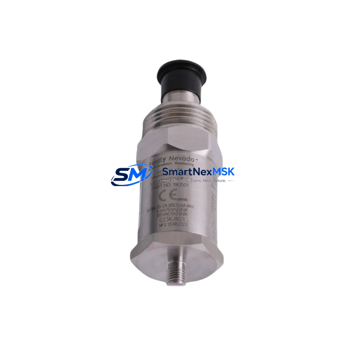
Bently Nevada 190501-01-99-04 Spare for Velomitor CT Automation: Spare Replacement & Industrial Downtime Risk Control
The Bently Nevada 190501-01-99-04 is a Velomitor CT piezoelectric velocity transducer engineered for continuous vibration monitoring on rotating machinery — including turbines, compressors, pumps, motors, and fans. As a maintenance-ready original spare, this unit supports rapid field replacement, minimizes unplanned downtime, and sustains the integrity of your condition monitoring infrastructure. Every unit is tested prior to shipment and backed by a 12-month warranty, making it a dependable choice for both planned maintenance cycles and emergency restoration scenarios.
For maintenance engineers managing aging machinery protection systems, the 190501-01-99-04 delivers direct compatibility with Bently Nevada 3300 and 3500 series monitoring racks. Its wide frequency response (2 Hz – 1,000 Hz) and robust 316 stainless-steel housing make it suitable for high-temperature, high-vibration industrial environments where sensor reliability is non-negotiable. Procurement engineers will appreciate the long-term supply commitment, documented traceability, and competitive lead times that accompany every unit dispatched from our dedicated spare parts inventory.
Spare Maintenance Table
| Parameter | Specification |
|---|---|
| Part Number / SKU | 190501-01-99-04 |
| Brand | Bently Nevada |
| Series | Velomitor CT |
| Sensor Type | Piezoelectric Velocity Transducer |
| Sensitivity | 100 mV/in/s (4 mV/mm/s) |
| Frequency Range | 2 Hz – 1,000 Hz (±3 dB) |
| Operating Temperature | -40°C to +121°C (-40°F to +250°F) |
| Output Signal | Voltage (mV) |
| Connector Type | 2-pin MIL-C-5015 style |
| Housing Material | 316 Stainless Steel |
| Mounting | 1/4-28 UNF threaded stud |
| Compatible Systems | Bently Nevada 3300, 3500 Series Monitoring Racks |
| Application | Turbines, Compressors, Pumps, Motors, Fans |
| Origin | United States |
| Warranty | 12 Months |
| Condition | Original Spare — Tested Before Shipment |
Maintenance Planning for Continuous Operation
When replacing the 190501-01-99-04 Velomitor CT transducer during a scheduled outage or emergency callout, a thorough inspection of the surrounding measurement loop is essential to prevent repeat failures and ensure signal integrity. Begin by verifying the condition of the interconnecting cable assembly — typically a Bently Nevada 330130 or 330180 series extension cable — checking for insulation damage, connector corrosion, and continuity before reinstalling the new transducer.
The signal conditioning path should also be reviewed. If the transducer feeds into a Bently Nevada 3500/42M velocity monitor module, inspect the I/O terminal block for loose wiring, oxidized contacts, and correct channel assignment. A faulty terminal block or degraded I/O module can mask a healthy transducer reading or generate false alarms that trigger unnecessary shutdowns. While the cabinet is open, inspect adjacent 3500/20 rack power supply modules and verify that output voltage rails are within specification — an under-voltage condition can corrupt velocity readings across multiple channels simultaneously.
For systems where the Velomitor CT feeds into a relay output module such as the Bently Nevada 3500/32 or 3500/33, verify that relay setpoints and time delays are correctly configured after replacement. A misconfigured relay can result in nuisance trips or, more critically, a failure to alarm on genuine machinery faults. If the monitoring rack communicates over Modbus or Ethernet to a DCS or SCADA platform, confirm that the 3500/92 communication gateway module is correctly mapping channel data after any hardware change.
In control cabinets where multiple transducer types coexist — for example, proximity probes such as the Bently Nevada 330103 alongside Velomitor CT velocity sensors — perform a full loop check on all channels in the affected rack section. Signal isolators or barriers installed between the transducer and the monitor input should also be inspected; degraded isolation can introduce ground loops that distort velocity amplitude readings. Finally, verify that the new transducer’s channel data is displaying correctly on any panel-mounted HMI or operator workstation, and confirm that no latched alarms remain active from the previous fault condition.
Site Replacement Workflow
Step 1 — Identify and Isolate: Confirm the exact mounting location of the 190501-01-99-04 on the machinery casing. Cross-reference the tag number against the P&ID and the Bently Nevada rack channel assignment. Isolate the channel at the monitor rack before disconnecting the transducer to prevent false trip signals from propagating to the DCS.
Step 2 — Remove and Inspect: Unscrew the transducer using the correct torque tool. Inspect the mounting surface for corrosion, thread damage, or contamination. Clean the mounting pad and verify flatness before installing the replacement unit. Check the cable connector for pin damage or moisture ingress.
Step 3 — Install and Torque: Thread the 190501-01-99-04 replacement into the mounting stud and torque to the manufacturer’s specification. Reconnect the extension cable and verify connector seating. Restore the channel at the monitor rack and confirm that the DC bias voltage on the transducer output is within the normal operating range (typically 8–12 VDC for Velomitor CT types).
Step 4 — Verify and Commission: With the machinery at rest, confirm that the velocity reading is at or near zero with no spurious noise. Bring the machine to operating speed and verify that vibration amplitude and frequency spectrum are consistent with historical baseline data. Document the replacement in the maintenance management system and update the spare parts inventory record.
Step 5 — Update Spare Stock: Replenish the consumed spare immediately to maintain minimum stock levels. For critical rotating machinery, a minimum of one-for-one replacement stock is recommended. Long lead times on OEM spares make pre-stocking the 190501-01-99-04 a prudent strategy for any facility operating Bently Nevada-based machinery protection systems.
Spare Parts Support FAQ
Q1: Is the 190501-01-99-04 a direct drop-in replacement for older Velomitor CT variants?
Yes. The 190501-01-99-04 is designed as a direct mechanical and electrical replacement for earlier Velomitor CT configurations used in Bently Nevada 3300 and 3500 series monitoring systems. Verify the connector type and cable assembly compatibility before installation. If your existing cable uses a different termination, a Bently Nevada-compatible adapter or replacement cable assembly may be required.
Q2: What pre-shipment testing is performed on each unit?
Every 190501-01-99-04 unit undergoes electrical continuity verification, sensitivity calibration check, and insulation resistance testing prior to dispatch. A test report is available upon request. Units are shipped in anti-static, moisture-resistant packaging to preserve condition during transit.
Q3: What does the 12-month warranty cover?
The 12-month warranty covers manufacturing defects, electrical failure under normal operating conditions, and sensitivity deviation beyond published tolerance. It does not cover damage resulting from incorrect installation, over-torquing, chemical exposure, or operation outside the specified temperature and vibration range. Warranty claims are processed with full technical support from our engineering team.
Q4: Can you support long-term or blanket purchase orders for this spare?
Yes. We maintain dedicated inventory for the 190501-01-99-04 and can support scheduled release orders, annual supply agreements, and emergency same-day dispatch for qualified accounts. Contact our sales team to discuss volume pricing, lead time commitments, and consignment stocking arrangements tailored to your maintenance planning cycle.
© 2026 SMARTNEXMSK. All rights reserved.
Original Source: https://smartnexmsk.com
Contact: [email protected] | +86 18259474341



