
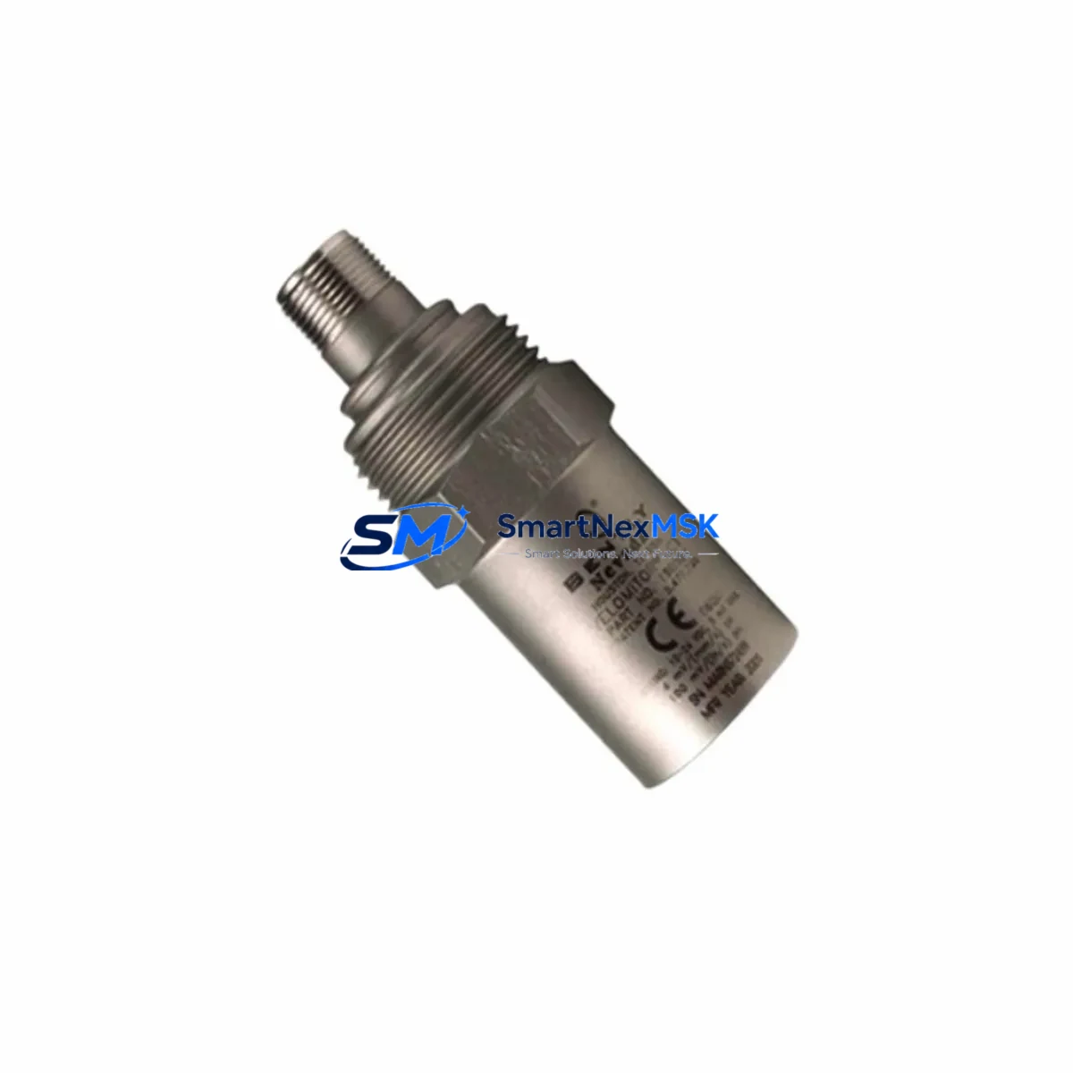
Bently Nevada 190501-04-00-00 Maintenance-Ready Spare for 3300 Automation
The Bently Nevada 190501-04-00-00 is an original Velomitor CT piezoelectric velocity transducer engineered for continuous vibration monitoring in rotating machinery. Designed for integration with the Bently Nevada 3300 Series monitoring platform, this transducer delivers reliable casing vibration measurements on turbines, compressors, pumps, fans, and motors operating in oil & gas, power generation, petrochemical, and heavy industrial environments.
For maintenance engineers managing both planned shutdowns and unplanned trips, the 190501-04-00-00 is a critical shelf spare. Its self-generating piezoelectric output eliminates the need for an external power supply or signal conditioner, simplifying the replacement workflow and reducing mean time to repair (MTTR) when a casing vibration channel goes into alarm or fault. Procurement engineers sourcing this unit benefit from a verified, tested replacement that ships with a 12-month warranty and full pre-shipment functional testing.
Spare Maintenance Table
| Parameter | Specification |
|---|---|
| Part Number / SKU | 190501-04-00-00 |
| Brand | Bently Nevada |
| Series | 3300 / Velomitor CT |
| Product Type | Piezoelectric Velocity Transducer |
| Measurement Type | Casing / Bearing Housing Vibration (velocity) |
| Output Type | Self-generating (no external power required) |
| Sensitivity | 100 mV/in/s (4 mV/mm/s) nominal |
| Frequency Range | 2 Hz to 1,000 Hz (±3 dB) |
| Operating Temperature | -40°C to +121°C |
| Connector Type | 2-pin MIL-C-5015 style (integral cable) |
| Mounting | Stud mount, 1/4-28 UNF or M8 adapter |
| Ingress Protection | IP67 |
| System Compatibility | Bently Nevada 3300 Series monitors (3300/16, 3300/20, 3300/25, 3300/46, 3300/55) |
| Application Environment | Turbine casing, compressor frame, pump bearing housing, motor end-bell |
| Origin | USA |
| Warranty | 12 Months — tested and verified before shipment |
Maintenance Planning for Continuous Operation
When a 190501-04-00-00 Velomitor CT is flagged during a routine point inspection or triggers a high-vibration alarm on the 3300 Series monitor, the replacement scope should extend beyond the transducer itself. A disciplined maintenance engineer will audit the full measurement chain and adjacent cabinet components to prevent repeat failures and confirm the restored reading is accurate.
Begin with the 3300 Series monitor card (such as the 3300/16 or 3300/20 velocity input card) that receives the Velomitor signal. Inspect the terminal block connections for loose field wiring — intermittent contact at the I/O strip is a common source of nuisance channel faults that are misdiagnosed as transducer failures. While the card is accessible, verify the 3300 XL rack power supply module output voltage; a sagging supply rail can shift the velocity channel baseline and produce apparent vibration offsets across multiple channels simultaneously.
Inspect the field signal cable routed from the transducer mounting point to the junction box or marshalling cabinet. Cables routed near exhaust casings, steam lines, or high-voltage conduit are vulnerable to insulation breakdown and shield continuity loss, both of which introduce noise into the velocity signal. Replace any cable showing jacket cracking, connector corrosion, or continuity loss at the same time as the transducer to avoid a second maintenance event.
If the machine also uses eddy current proximity probes (such as the 330103 or 330105 series) for shaft radial vibration monitoring, verify those channels simultaneously. Casing velocity and shaft proximity measurements share the same 3300 rack infrastructure, and a wiring fault on one channel can induce crosstalk on adjacent channels in older rack configurations. Check the associated 330180 Series Proximitor Sensor gap voltages to confirm no secondary faults have developed during the same maintenance window.
For machines equipped with a Keyphasor module (3300/25 or 3500/17), confirm the Keyphasor probe gap and signal integrity after any bearing housing work. Phase reference accuracy directly affects 1X and 2X vibration vector calculations used in balancing and alignment diagnostics — a disturbed Keyphasor signal will corrupt trend data across the entire machine train.
At the marshalling cabinet level, inspect terminal blocks and DIN rail fuse holders serving the velocity monitoring loop. Blown fuses or corroded terminal contacts are a frequent root cause of channel loss that is only discovered during a transducer swap. Also audit any signal isolators or barriers installed between the field device and the monitor input — degraded isolators can attenuate the velocity signal and produce falsely low vibration readings that mask developing faults.
Finally, update your spare parts inventory record to reflect the consumed transducer and initiate a replenishment order. Best practice for critical rotating machinery is to maintain a minimum of two 190501-04-00-00 units per machine train on the shelf, alongside matched field cables and at least one spare monitor card per rack.
Site Replacement Workflow
Step 1 — Isolation and documentation: Before removing the transducer, record the existing channel reading from the 3300 Series monitor display or DCS historian. Note the channel number, machine tag, mounting location, and current vibration trend in the maintenance work order. This baseline confirms the pre-fault condition and serves as the acceptance criterion for the replacement unit.
Step 2 — Mechanical removal: De-energize the monitoring loop if required by site LOTO procedures. Disconnect the field cable at the transducer connector. Unscrew the transducer from the stud mount — do not apply torque to the cable body. Inspect the mounting surface for corrosion, thread damage, or accumulated deposits that may have contributed to signal degradation.
Step 3 — New transducer installation: Thread the 190501-04-00-00 onto the cleaned stud mount and torque to the specified value (typically 15–20 in-lb for 1/4-28 UNF). Route the cable away from heat sources and high-voltage conduit. Secure with cable ties at existing clamp points. Reconnect the field cable at the junction box or terminal block.
Step 4 — Electrical verification: With the monitoring loop energized, confirm the channel returns a valid velocity reading on the 3300 Series monitor. Verify the reading is within the expected baseline range for the machine at its normal operating speed. Confirm the monitor channel clears any latched alerts and the DCS point returns to a healthy state.
Step 5 — Functional test and sign-off: Perform a bump test or slow-roll check if site procedures permit to confirm transducer response. Document the as-left vibration reading, update the CMMS work order, and return the failed unit for failure analysis or disposal per site procedures. The 190501-04-00-00 is a direct mechanical and electrical replacement for legacy Velomitor CT units in existing 3300 Series installations, requiring no bracket modification or monitor reconfiguration.
Spare Parts Support FAQ
Q1: Is the 190501-04-00-00 compatible with both 3300 Series and 3500 Series monitors?
The 190501-04-00-00 Velomitor CT is a self-generating velocity transducer compatible with any monitor that accepts a passive velocity input, including the Bently Nevada 3300 Series velocity cards and the 3500/42 velocity/acceleration monitor. Confirm the monitor card’s input impedance and sensitivity range match the transducer specification before installation. No Proximitor or external signal conditioner is required.
Q2: What is the recommended spare parts stocking strategy for this transducer?
For critical machinery (turbines, compressors, large pumps), maintain a minimum of two 190501-04-00-00 units per machine train plus one spare field cable per monitored point. For non-critical or standby equipment, one unit per machine train is acceptable. Store in original packaging in a dry, temperature-controlled environment and inspect annually for connector corrosion and cable jacket integrity.
Q3: How is each unit tested before shipment?
Every 190501-04-00-00 unit is bench-tested prior to shipment using a calibrated shaker table or signal simulator to verify output sensitivity (100 mV/in/s ±10%), frequency response, and connector integrity. A test report is available upon request. Units are shipped in anti-static, padded packaging to prevent damage in transit.
Q4: What does the 12-month warranty cover?
The 12-month warranty covers manufacturing defects, output sensitivity drift beyond OEM specification, and connector failure under normal operating conditions. It does not cover physical damage from improper installation, mechanical impact, or chemical exposure. Warranty claims are processed within 5 business days with advance replacement available for critical applications to minimize downtime.
© 2026 SMARTNEXMSK. All rights reserved.
Original Source: https://smartnexmsk.com
Contact: [email protected] | +86 18259474341



