
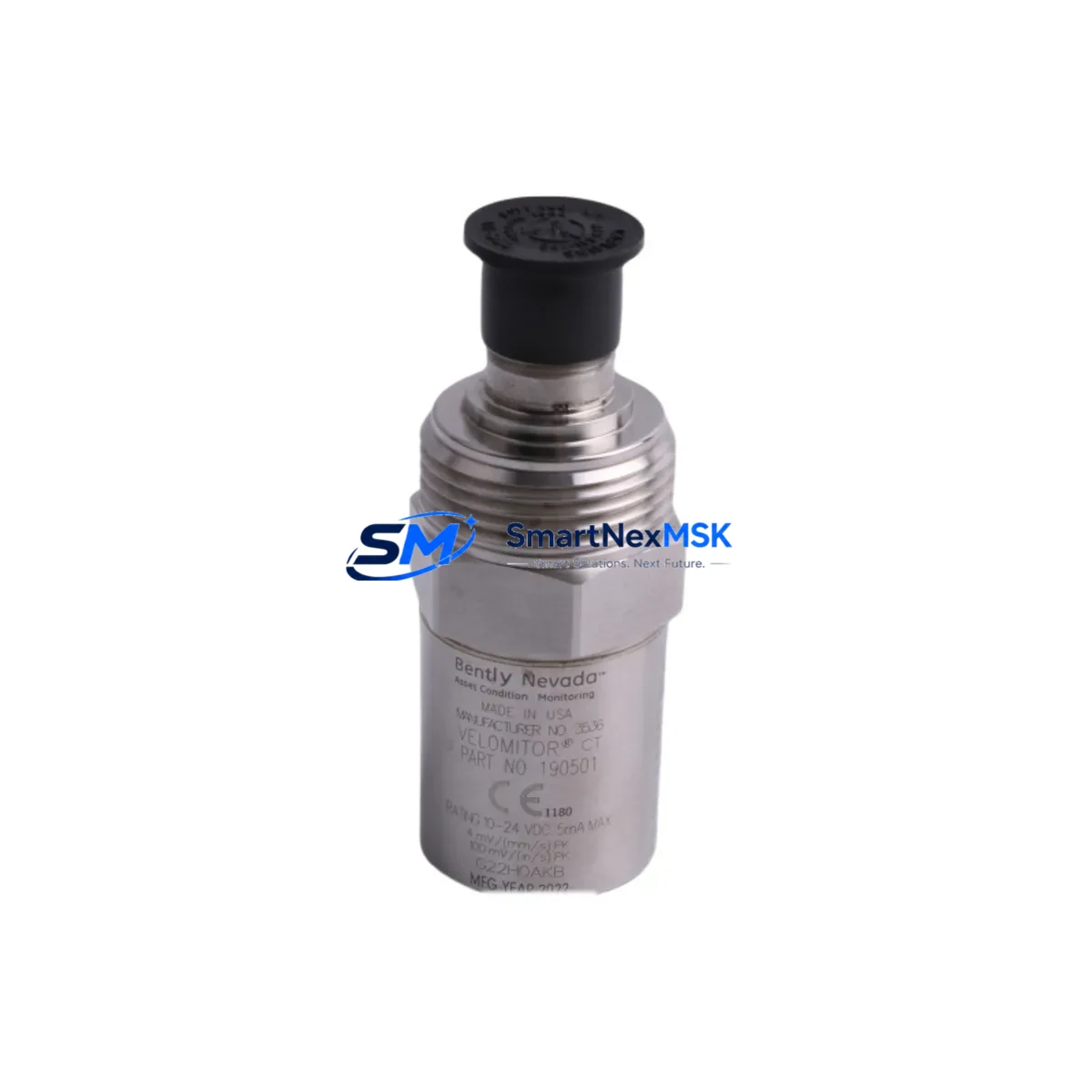
Bently Nevada 190501-05-00-CN Retrofit Velocity Transducer: Compatible Upgrade for Legacy Seismic Monitoring Systems
The Bently Nevada 190501-05-00-CN is a Velomitor CT piezoelectric velocity transducer engineered for direct retrofit into existing Bently Nevada 3500 Series machinery protection systems and legacy continuous monitoring platforms. Designed to replace discontinued or end-of-life seismic velocity sensors without requiring rack reconfiguration, this unit delivers a smooth migration path for facilities managing aging vibration monitoring infrastructure. Whether you are upgrading a turbine protection panel, replacing a failed sensor on a compressor train, or modernizing a control cabinet that has been in service for over a decade, the 190501-05-00-CN provides the electrical and mechanical compatibility needed to restore full system functionality with minimal downtime.
The Velomitor CT series uses an integrated circuit piezoelectric (ICP) design that outputs a low-impedance voltage signal proportional to vibration velocity. This signal format is directly compatible with the Bently Nevada 3500/42M Proximitor/Seismic Monitor module, allowing the transducer to be connected to existing field wiring without signal conditioning changes. Engineers replacing older Velomitor XA or standard Velomitor units will find that the 190501-05-00-CN maintains the same connector pinout and cable routing conventions, significantly reducing the scope of field work during a planned outage.
Upgrade Compatibility Table
| Parameter | Details |
|---|---|
| SKU / Part Number | 190501-05-00-CN |
| Brand / Series | Bently Nevada / Velomitor CT |
| Replaces / Supersedes | Velomitor XA, 190501-01-00-CN, legacy seismic velocity transducers in 3500 rack systems |
| Compatible Monitor Modules | Bently Nevada 3500/42M, 3500/42E Proximitor/Seismic Monitor |
| Signal Output | ICP (Integrated Circuit Piezoelectric), low-impedance voltage |
| Connector Interface | 2-pin MIL-C-5015 style, compatible with standard Velomitor field cables |
| Mounting | Stud mount (10-32 UNF), direct replacement for existing mounting pads |
| Communication Compatibility | Analog signal; integrates with 3500 rack Modbus/TCP and System 1 via existing monitor modules |
| Installation Requirement | No rack reconfiguration required; verify bias voltage and constant current supply from monitor module |
| Commissioning Focus | Confirm bias voltage (typically 8–12 VDC), check cable shield grounding, validate alarm setpoints in 3500/42M configuration |
| Warranty | 12-Month Warranty from date of shipment |
Retrofit Planning for Existing Automation Systems
Successful retrofit of the 190501-05-00-CN into an operating plant begins well before the maintenance window opens. The first step is a thorough review of the existing 3500 rack configuration. Technicians should document the current channel assignments on the Bently Nevada 3500/42M Proximitor/Seismic Monitor module, noting the configured full-scale range, alarm trip setpoints, and whether the channel is operating in velocity or displacement mode. If the rack also houses a 3500/20 Rack Interface Module, confirm that the System 1 software database reflects the correct transducer type before swapping the sensor, as a mismatch will generate false alerts during startup.
Field wiring is the next critical checkpoint. The 190501-05-00-CN uses the same two-conductor shielded cable convention as earlier Velomitor models, but engineers should inspect the existing Bently Nevada 330130 or 330180 extension cable for insulation degradation, especially in high-temperature or chemically aggressive environments. If the cable run exceeds the recommended length, signal attenuation may affect the bias voltage reading at the monitor input. In such cases, replacing the extension cable in parallel with the transducer swap eliminates a common source of post-retrofit nuisance trips.
For facilities that are simultaneously upgrading their protection logic, the retrofit window is an ideal time to review the 3500/33 16-Channel Relay Module trip relay assignments and verify that the new transducer’s sensitivity matches the alarm engineering units configured in the rack. Plants migrating from older analog-only architectures to networked condition monitoring should also confirm that the 3500/92 Communication Gateway Module firmware is current, as older gateway versions may not correctly parse velocity channel data from updated monitor modules.
Where the control cabinet also contains a Bently Nevada 3500/15 Power Supply Module, verify that the available constant current output (typically 2–20 mA) is within the operating range required by the 190501-05-00-CN. Insufficient bias current is a frequent root cause of intermittent signal loss after transducer replacement and is easily confirmed with a handheld multimeter before the machine is returned to service. If the power supply is aging or showing voltage ripple, replacing it concurrently with the transducer is a cost-effective decision that avoids a second outage.
Plants running GE System 1 Evolution or the legacy System 1 condition monitoring platform should update the asset database to reflect the new transducer serial number and calibration sensitivity (mV/mm/s or mV/in/s) immediately after installation. This ensures that trend data continuity is maintained and that the software does not flag the new sensor as an unconfigured device. If the facility also uses a Bently Nevada TK-3 or TK-81 portable data collector for route-based measurements on the same machine train, update the route database to match the new transducer sensitivity before the next scheduled data collection round.
Downtime Control During System Migration
Minimizing production impact during a seismic transducer replacement requires a structured pre-outage preparation protocol. Before the machine is taken offline, download and archive the complete 3500 rack configuration using Rack Configuration Software (RCS). This backup preserves all channel parameters, alarm setpoints, and relay logic, allowing the configuration to be restored in minutes if a module swap is required during the same outage window. Store the configuration file on a dedicated engineering workstation and on a removable drive kept in the control room.
During the outage, follow a defined sequence: isolate the channel at the 3500/42M monitor module first (place the channel in bypass mode if the rack supports it), then disconnect the field cable at the junction box, remove the old transducer, install the 190501-05-00-CN, reconnect the cable, and restore the channel from bypass. This sequence prevents spurious trip signals from propagating to the relay module while the transducer is disconnected. If the rack does not support per-channel bypass, coordinate with the control room to temporarily inhibit the associated trip relay at the 3500/33 before beginning work.
After installation, perform a bench-level verification by checking the bias voltage at the monitor module input terminals. A reading within the normal operating window (typically 8–12 VDC for ICP-type transducers) confirms that the transducer and cable are functioning correctly before the machine is restarted. Document the as-found and as-left bias voltage readings in the maintenance record. Once the machine is back online, monitor the vibration trend for the first 30 minutes of operation to confirm that the signal is stable and that no alarm thresholds are being approached due to installation-induced mechanical effects such as improper stud torque or cable strain.
Retrofit Support FAQ
Q1: Is the 190501-05-00-CN a direct drop-in replacement for the Velomitor XA?
Yes. The 190501-05-00-CN shares the same mounting thread (10-32 UNF stud), connector type, and ICP signal format as the Velomitor XA series. No changes to the monitor module configuration or field wiring are required in most installations. Verify the transducer sensitivity specification (mV/mm/s) matches the value configured in the 3500/42M channel setup to ensure alarm setpoints remain accurate after replacement.
Q2: What pre-shipment testing is performed on the 190501-05-00-CN?
Each unit undergoes functional verification including bias voltage output, frequency response check across the rated bandwidth, and sensitivity calibration confirmation prior to shipment. A test report is available upon request. Units are shipped in anti-static, impact-resistant packaging to prevent transit damage to the piezoelectric element.
Q3: Can this transducer be used with non-Bently Nevada monitor systems?
The 190501-05-00-CN outputs a standard ICP-compatible low-impedance voltage signal and can operate with any monitor module that provides a compatible constant current excitation source (2–20 mA) and accepts a voltage input in the transducer’s output range. Compatibility with third-party systems such as Emerson CSI or Rockwell Automation vibration monitors should be verified against the respective monitor module’s input specifications before installation.
Q4: What does the 12-month warranty cover?
The 12-month warranty covers manufacturing defects in materials and workmanship from the date of shipment. It does not cover damage resulting from improper installation, over-torquing of the mounting stud, exposure to fluids beyond the rated ingress protection, or electrical overstress. Warranty claims are processed with return authorization; replacement units are dispatched within 5 business days of claim approval. Contact [email protected] for warranty support.
© 2026 SMARTNEXMSK. All rights reserved.
Original Source: https://smartnexmsk.com
Contact: [email protected] | +86 18259474341



