
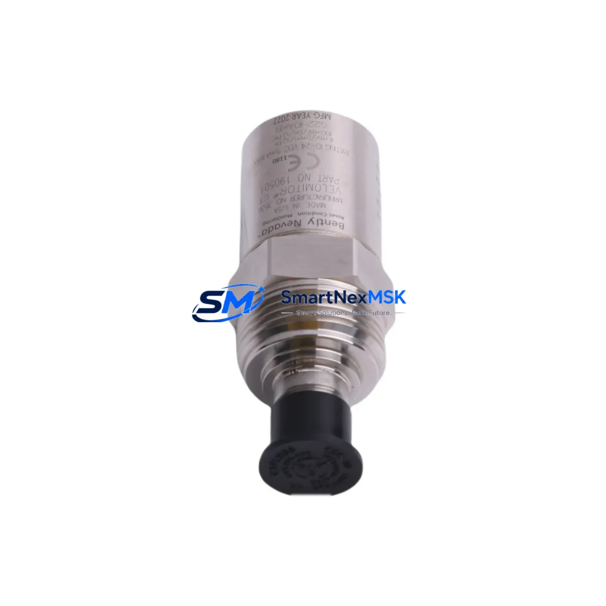
Bently Nevada 190501-06-00-CN Velomitor CT Retrofit: Compatible Modernization for Legacy Vibration Monitoring Systems
The Bently Nevada 190501-06-00-CN Velomitor CT is a high-performance velocity transducer engineered for continuous vibration monitoring on rotating machinery. As legacy Bently Nevada 3300 and 3500 series monitoring systems age out of active production support, plant engineers and reliability teams face increasing pressure to source compatible replacement units that preserve existing wiring infrastructure, signal conditioning chains, and alarm setpoint logic without triggering a full system overhaul.
This retrofit-ready 190501-06-00-CN unit is sourced from verified supply channels, functionally tested prior to shipment, and backed by a 12-month warranty. It is designed to serve as a direct drop-in replacement for the original Bently Nevada Velomitor CT transducer in applications where the monitoring rack, junction box wiring, and DCS or PLC input cards remain in service.
Upgrade Compatibility Table
| Parameter | 190501-06-00-CN (This Unit) | Retrofit Notes |
|---|---|---|
| Output Signal | 4–20 mA velocity proportional | Compatible with existing Bently Nevada 3300/3500 input modules |
| Connector Type | MIL-C-5015 style, 2-pin | Matches original field wiring; no re-termination required |
| Mounting | Stud mount, 1/4-28 UNF | Direct bolt-on to existing machinery pad; no machining needed |
| Frequency Range | 2–1000 Hz | Covers standard rotating equipment monitoring bands |
| Communication Compatibility | Analog 4–20 mA (passive) | Compatible with DCS analog input cards and PLC AI modules |
| Replacement Target | 190501-06-00-CN (OEM) | Functional equivalent; verify cable length suffix if applicable |
| Installation Requirement | No special tools; standard torque wrench | Follow OEM torque spec; apply thread sealant if required |
| Commissioning | Zero-speed check, loop calibration | Verify 4 mA at rest; confirm alarm setpoints in monitoring rack |
| Warranty | 12 Months | Covers manufacturing defects; includes pre-shipment functional test |
Retrofit Planning for Existing Automation Systems
When integrating the 190501-06-00-CN into an existing control architecture, the retrofit scope typically extends beyond the transducer itself. In a Bently Nevada 3500 series monitoring rack, the transducer feeds signal into a 3500/42M Proximitor/Seismic Monitor module or a 3500/46M Hydro Monitor, depending on the machine type. Before swapping the Velomitor CT, engineers should confirm that the monitor module’s input configuration — including full-scale range, alarm setpoints, and OK relay logic — is documented and backed up using System 1 software or the rack’s configuration utility.
In plants where the Bently Nevada rack interfaces with a DCS via a 3500/92 Communication Gateway or a Modbus TCP bridge, the retrofit should include a communication link verification step. The gateway’s tag mapping and polling rate should be confirmed against the DCS historian to ensure no data gaps occur during the transducer swap window. If the plant uses a Rockwell Automation ControlLogix or CompactLogix PLC for machine protection interlock logic, the analog input channel receiving the 4–20 mA velocity signal should be placed in manual override or bypass mode during the physical swap to prevent nuisance trips.
For older installations where the Velomitor CT cable runs through a junction box before reaching the monitoring rack, inspect the terminal block condition and cable shield continuity. Corroded terminals or broken shields are a common source of signal noise that can be misattributed to a faulty transducer. Replacing the 190501-06-00-CN without addressing wiring integrity issues will not resolve intermittent alarm conditions. In such cases, pairing the transducer replacement with a terminal block refresh — such as Phoenix Contact or Weidmuller DIN-rail terminal strips — is recommended practice.
Where the plant’s control cabinet houses a Bently Nevada 3300 series rack alongside a Siemens S7-300 or S7-400 PLC handling process control, the I/O mapping between the vibration monitoring system and the PLC’s analog input module (SM 331 or equivalent) should be verified before and after the swap. If the plant is in the process of migrating from S7-300 to S7-1500, the 190501-06-00-CN’s analog output is fully compatible with the new generation ET 200SP distributed I/O analog input modules, making it a viable transducer choice across both legacy and modernized control platforms.
In turbine and compressor applications where the Velomitor CT is used alongside proximity probes and keyphasor transducers — such as the Bently Nevada 330180 proximity probe or the 330130 series — the retrofit plan should include a full channel-by-channel verification of the monitoring rack’s OK status after the new transducer is installed and the loop is energized. HMI screens on the operator workstation should be reviewed to confirm that velocity trend displays and alarm banners reflect the new transducer’s signal correctly, particularly if the HMI is running on a Wonderware InTouch or Ignition SCADA platform with hardcoded tag scaling.
Downtime Control During System Migration
Minimizing unplanned downtime during a Velomitor CT replacement requires a structured pre-outage preparation protocol. Before the maintenance window opens, the replacement 190501-06-00-CN should be bench-tested using a signal simulator to confirm the 4–20 mA output curve is within specification. This pre-shipment functional test is included with every unit we supply, and the test record is available upon request.
During the outage window, the recommended sequence is: isolate the monitoring channel at the rack, disconnect the field cable at the junction box, remove the old transducer, install the 190501-06-00-CN to the correct torque specification, reconnect the field cable, re-energize the loop, and verify the OK status at the rack front panel before restoring the channel to active monitoring. This sequence typically takes 20–40 minutes per transducer point when the replacement unit is on-hand and the field wiring is in good condition.
To protect original program logic during the migration, ensure that the PLC or DCS program backup is current before the outage begins. If the monitoring rack’s configuration has been modified since the last backup, export the current configuration using the rack’s configuration software before powering down. This protects alarm setpoints, full-scale ranges, and relay output assignments that may have been field-adjusted over the years and are not reflected in the original commissioning documentation.
For plants operating continuous processes where even a brief monitoring gap is unacceptable, a temporary portable vibration data collector can be used to maintain trend data continuity during the swap window. This approach is particularly valuable in petrochemical and power generation facilities where regulatory requirements mandate continuous machinery protection coverage.
Retrofit Support FAQ
Q: Is the 190501-06-00-CN a direct drop-in replacement for the original Bently Nevada Velomitor CT?
A: Yes. The 190501-06-00-CN is a functional equivalent to the original OEM unit. It uses the same connector type, mounting thread, output signal range, and frequency response. No wiring modifications or rack reconfiguration are required for a standard replacement. Verify the cable length suffix on your existing unit if your installation uses an integral cable version.
Q: What commissioning steps are required after installation?
A: After installation, energize the loop and verify a 4 mA output at zero velocity (machine at rest). Confirm the OK relay status at the monitoring rack. Check the velocity trend display on the operator HMI for a clean, noise-free signal. If the plant uses a Bently Nevada System 1 condition monitoring platform, verify that the new transducer’s channel data is being logged correctly before closing the work order.
Q: Can this unit be used with non-Bently Nevada monitoring systems?
A: Yes. The 190501-06-00-CN outputs a standard 4–20 mA analog signal that is compatible with any monitoring system or PLC analog input module that accepts this signal type, including Emerson, Honeywell, Siemens, Rockwell Automation, and Yokogawa platforms. Signal conditioning and scaling should be configured at the receiving system to match the transducer’s sensitivity specification.
Q: What does the 12-month warranty cover?
A: The 12-month warranty covers manufacturing defects and functional failures under normal operating conditions. Each unit undergoes a pre-shipment functional test, and the test record is available upon request. Warranty claims are processed through our technical support team. Units damaged by incorrect installation, overvoltage, or mechanical impact are not covered under the standard warranty terms.
© 2026 SMARTNEXMSK. All rights reserved.
Original Source: https://smartnexmsk.com
Contact: [email protected] | +86 18259474341



