
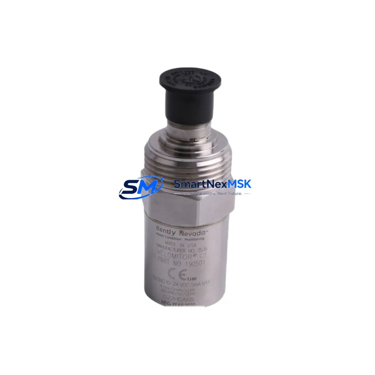
Bently Nevada 190501-10-00-01 Retrofit-Ready Velocity Transducer for 3300 Series Control Systems
The Bently Nevada 190501-10-00-01 Velomitor CT is a high-performance velocity transducer engineered for seamless integration into legacy and modern vibration monitoring architectures. As a direct retrofit replacement for discontinued or end-of-life Velomitor CT units, this module supports smooth migration within Bently Nevada 3300 Series monitoring systems without requiring hardware redesign or rack reconfiguration. Whether you are managing a planned upgrade, responding to an unplanned failure, or executing a phased modernization of your rotating machinery protection infrastructure, the 190501-10-00-01 delivers the signal fidelity and mechanical compatibility your system demands.
This transducer is designed for industrial environments where continuous vibration monitoring of turbines, compressors, pumps, and motors is critical to plant safety and uptime. It outputs a velocity signal compatible with the Bently Nevada 3300 XL 11 mm Proximity Transducer System and integrates directly with 3300/16 and 3300/20 monitor cards without firmware modification. Engineers replacing aging Velomitor CT units in existing control cabinets will find that terminal wiring, cable routing, and connector pinouts are preserved, significantly reducing commissioning time and the risk of wiring errors during cutover.
Upgrade Compatibility Table
| Parameter | 190501-10-00-01 (This Unit) | Notes / Retrofit Guidance |
|---|---|---|
| Compatible Monitor Series | Bently Nevada 3300 Series | Direct replacement; no rack modification required |
| Signal Output | Velocity (mV/mm/s) | Matches legacy Velomitor CT output specification |
| Connector / Terminal | Standard Velomitor CT pinout | Existing field wiring reusable; verify polarity before energizing |
| Mounting Interface | Standard industrial thread mount | Confirm thread spec (M8 or 1/4-28 UNF) against existing bracket |
| Power Supply Requirement | 18–30 VDC (loop-powered) | Verify barrier or isolator output capacity before installation |
| Communication Compatibility | Analog 4–20 mA / voltage output | Compatible with existing 3300 monitor input cards |
| Backplane / Rack Interface | Not applicable (field-mount transducer) | Cable length and impedance must be verified for long runs |
| Replacement Recommendation | Direct drop-in for 190501-10-00-01 | No program changes required in monitor configuration |
| Commissioning Focus | Zero-speed check, full-speed vibration baseline | Compare against historical trend data post-installation |
| Warranty | 12 Months | Covers manufacturing defects; includes pre-shipment functional test |
Retrofit Planning for Existing Automation Systems
Successful retrofit of the Bently Nevada 190501-10-00-01 into an operating plant requires a structured approach that accounts for the full signal chain from transducer to control room. Before removing the existing Velomitor CT, engineers should document the current vibration baseline using the 3300/16 monitor card’s trend display and archive the configuration via the System 1 software platform if installed. This preserves the historical reference needed to validate the replacement unit’s performance post-commissioning.
In most 3300 Series installations, the transducer connects through a Bently Nevada 990 Vibration Transmitter or directly to a 3300/20 monitor input. When replacing the 190501-10-00-01, verify that the associated Proximitor or signal conditioner — such as the 3300 XL 8 mm Proximity Transducer System — is functioning correctly, as a degraded conditioner can mask transducer faults or produce erroneous readings after replacement. Similarly, inspect the junction box terminals and field cable for insulation breakdown, particularly in high-temperature or high-humidity environments common in turbine halls and compressor stations.
For plants running a Bently Nevada 3500 Series rack in parallel or as a migration target, note that the 190501-10-00-01 is also compatible with 3500/42M Velocity/Acceleration Monitor inputs, allowing it to serve as a bridging transducer during phased migration from 3300 to 3500 architecture. This is particularly valuable when the control system upgrade is being staged across multiple outage windows. During this period, the 3500 Rack Interface Module and associated I/O terminal blocks should be pre-staged and tested offline before the live cutover.
Where the plant uses a DCS such as Honeywell Experion PKS or Emerson DeltaV for high-level integration, confirm that the 4–20 mA output from the 3300 monitor card is correctly mapped to the DCS analog input module. Tag renaming in the DCS historian and HMI faceplate updates should be completed before the cutover window to avoid alarm suppression gaps. If the plant uses a Rockwell Automation ControlLogix or CompactLogix PLC for machinery protection relay logic, verify that the analog input scaling in the PLC program matches the new transducer’s sensitivity specification.
Cable management is a frequently overlooked element of Velomitor CT replacement. The 190501-10-00-01 uses a standard coaxial or shielded twisted-pair cable depending on installation configuration. Ensure the cable shield is grounded at one end only to prevent ground loops that can introduce noise into the velocity signal. For installations where the original cable run exceeds 30 meters, verify signal attenuation against the monitor card’s input impedance specification before finalizing the replacement plan.
Downtime Control During System Migration
Minimizing unplanned downtime during Velomitor CT replacement requires pre-staging the 190501-10-00-01 and all associated hardware — including terminal blocks, cable glands, and mounting hardware — before the maintenance window opens. A parallel hot-swap approach is recommended where plant safety systems permit: install the new transducer on a temporary bracket adjacent to the existing unit, verify signal output against the live reading, then perform the final cutover with the machine at rest during a scheduled outage.
Before de-energizing the existing transducer, place the associated 3300 monitor channel in bypass mode to prevent spurious machinery protection trips during the swap. Document the bypass action in the plant’s permit-to-work system and notify the control room operator. After installing the 190501-10-00-01, restore the monitor channel from bypass only after confirming a stable, noise-free velocity signal at the expected baseline level. Compare the post-installation reading against the archived trend data to confirm the replacement unit is performing within specification.
For plants where the 3300 Series monitor is integrated with a safety instrumented system (SIS) via a Bently Nevada 3500/33 16-Channel Relay Module or equivalent, coordinate the bypass and restoration sequence with the SIS engineer to ensure functional safety integrity is maintained throughout the replacement procedure. All bypass and restoration actions should be logged with timestamps for audit and compliance purposes.
Pre-shipment functional testing of the 190501-10-00-01 is performed at our facility before dispatch, and a test report is available upon request. The 12-month warranty covers manufacturing defects and includes technical support for installation and commissioning queries.
Retrofit Support FAQ
Q1: Is the 190501-10-00-01 a direct drop-in replacement for the original Bently Nevada Velomitor CT?
Yes. The 190501-10-00-01 is dimensionally and electrically compatible with the original Velomitor CT specification. Terminal wiring, connector pinout, and signal output characteristics are preserved, allowing direct replacement without modification to the existing cable or monitor configuration.
Q2: What commissioning checks are required after installation?
After installation, verify the DC bias voltage at the monitor input is within the specified range (typically 8–12 VDC for Velomitor CT configurations). Perform a zero-speed check to confirm the noise floor is within specification, then monitor the vibration trend during machine run-up to confirm the signal matches the pre-replacement baseline. Any deviation greater than 10% should be investigated before returning the channel to normal monitoring mode.
Q3: Can this transducer be used with a Bently Nevada 3500 Series rack?
Yes. The 190501-10-00-01 is compatible with 3500/42M Velocity/Acceleration Monitor inputs, making it suitable for plants migrating from 3300 to 3500 Series architecture. Confirm the monitor card’s input configuration matches the transducer’s sensitivity and output range before energizing.
Q4: What does the 12-month warranty cover, and is pre-shipment testing included?
The 12-month warranty covers manufacturing defects in materials and workmanship from the date of shipment. Each unit undergoes functional testing before dispatch, and a test report is available upon request. Warranty claims are supported by our technical team at [email protected].
© 2026 SMARTNEXMSK. All rights reserved.
Original Source: https://smartnexmsk.com
Contact: [email protected] | +86 18259474341



