
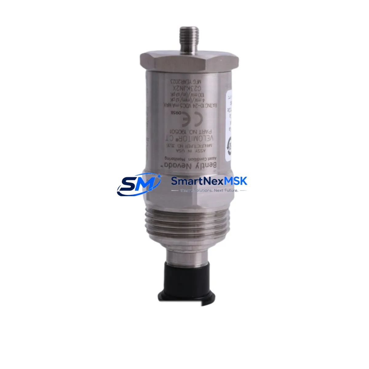
Bently Nevada 190501-10-00-04 Maintenance-Ready Spare for Velomitor CT Automation
The Bently Nevada 190501-10-00-04 is an original Velomitor CT velocity transducer engineered for continuous vibration monitoring in rotating machinery and industrial automation systems. As a maintenance-ready spare, it is designed to support rapid field replacement, minimize unplanned downtime, and sustain the integrity of condition monitoring loops in critical plant environments. Whether you are managing a scheduled turnaround, responding to an emergency shutdown, or building a proactive spare parts inventory, the 190501-10-00-04 delivers the measurement accuracy and mechanical reliability that maintenance and procurement engineers depend on.
This unit is fully compatible with Bently Nevada 3300 and 3500 series monitoring systems, making it a direct drop-in replacement for aging or failed transducers without requiring reconfiguration of the monitoring rack. Its integrated cable and connector design reduces installation time on-site, and its hermetically sealed housing ensures reliable performance in high-vibration, high-temperature, and chemically aggressive environments typical of oil and gas, power generation, petrochemical, and heavy manufacturing facilities.
Spare Maintenance Table
| Parameter | Specification |
|---|---|
| Part Number | 190501-10-00-04 |
| Brand | Bently Nevada |
| Series | Velomitor CT |
| Product Type | Velocity Transducer (Seismic) |
| Sensitivity | 100 mV/in/s (4 mV/mm/s) |
| Frequency Range | 2 to 1000 Hz |
| Operating Temperature | -40°C to +121°C |
| Supply Voltage | 18–30 VDC (loop powered) |
| Output Signal | 4–20 mA / Voltage |
| Connector Type | 2-pin MIL-C-5015 style |
| Housing Material | Stainless Steel, hermetically sealed |
| Mounting | Stud mount, 1/4-28 UNF |
| Compatibility | Bently Nevada 3300 XL, 3500 Series monitors |
| Origin | USA |
| Application | Rotating machinery, turbines, compressors, pumps |
| Warranty | 12 Months |
| Condition | Original, factory-tested |
| Shipping | Tested before dispatch, global delivery |
Maintenance Planning for Continuous Operation
When replacing the 190501-10-00-04 Velomitor CT transducer during a planned or emergency maintenance event, a thorough inspection of the surrounding measurement and protection circuit is essential to ensure the system returns to full operational status without latent faults. Maintenance engineers should begin by verifying the integrity of the interconnecting cable assembly — typically a Bently Nevada 330130 or 330180 series extension cable — checking for insulation breakdown, connector corrosion, or mechanical damage caused by vibration fatigue over extended service cycles.
The 3500/42M Proximitor/Seismic Monitor or the 3300 XL monitor card that processes the transducer signal should be inspected for alarm setpoint drift, channel fault indicators, and firmware version compatibility. If the monitor card has been in service for more than five years, it is advisable to cross-reference its calibration records and consider stocking a spare 3500/42M module alongside the transducer to avoid a secondary failure during the same outage window.
Power supply integrity is a frequently overlooked factor in transducer replacement workflows. The 3500 rack’s power supply module — such as the 3500/15 Power Supply — should be load-tested to confirm stable 24 VDC output, as voltage sag or ripple can cause erratic velocity readings even with a new transducer installed. Similarly, the I/O module terminal blocks and field wiring should be inspected for loose terminations, oxidized contacts, or incorrect shielding grounding, all of which can introduce noise into the velocity signal chain.
For facilities operating legacy DCS or safety instrumented systems, the 4–20 mA output from the 190501-10-00-04 is typically routed through a signal isolator or barrier — such as a Pepperl+Fuchs KFD2-STV4 or equivalent — before entering the DCS analog input card. These isolators should be tested for loop resistance compliance and output linearity as part of the replacement procedure. If the plant uses a Bently Nevada System 1 software platform for condition monitoring, the channel configuration and alert thresholds should be verified and re-commissioned after transducer swap to ensure alarm logic integrity.
Procurement engineers building or refreshing a spare parts inventory for rotating machinery protection systems should consider stocking the 190501-10-00-04 alongside complementary components: a 3300 XL 8mm proximity probe and driver for shaft displacement monitoring, a 330180 extension cable for field routing flexibility, a 3500/22M Transient Data Interface for advanced diagnostics, and a set of terminal block connectors and fuse holders rated for the control cabinet’s protection circuit. Maintaining a minimum of two Velomitor CT units per critical machine train is a widely adopted best practice in ISO 13373-compliant maintenance programs.
Site Replacement Workflow
The 190501-10-00-04 is designed to replace the legacy 190501-10-00-01 and 190501-10-00-02 variants without modification to the monitor rack configuration, provided the cable assembly and connector pinout are verified prior to installation. On-site replacement follows a standard sequence: isolate the monitoring channel at the 3500 rack, disconnect the field cable at the transducer junction box, remove the old transducer from its stud mount, clean the mounting surface, install the 190501-10-00-04 to the specified torque value, reconnect the cable assembly, and restore the monitoring channel.
After installation, perform a static loop check by verifying the 4–20 mA output at the monitor card input terminals against a known reference velocity source or by using a Bently Nevada calibration simulator. Confirm that the System 1 or DCS historian is logging the channel correctly and that no latent alarms are present before returning the machine to service. This structured workflow typically reduces total replacement time to under two hours for a single transducer, significantly limiting the production impact of an unplanned vibration monitoring failure.
For older plant installations where the original Velomitor CT mounting boss has corroded or been damaged, a stainless steel mounting adapter is available to restore the 1/4-28 UNF thread interface without requiring machining of the machine casing. This approach is particularly valuable in life-extension projects for equipment operating beyond its original design life, where maintaining the existing monitoring architecture is more cost-effective than a full system upgrade.
Spare Parts Support FAQ
Q: Is the 190501-10-00-04 a direct replacement for older Velomitor CT part numbers?
A: Yes. The 190501-10-00-04 is backward compatible with earlier Velomitor CT variants including the -01 and -02 suffixes. Electrical interface, sensitivity, and connector type are identical, allowing direct substitution in existing 3300 and 3500 series monitor installations without reconfiguration.
Q: What is the warranty coverage and how is it validated?
A: Every 190501-10-00-04 unit supplied by SMARTNEXMSK carries a 12-month warranty from the date of shipment. Each unit is tested prior to dispatch and accompanied by a test report. Warranty claims are supported by our technical team via [email protected] with a typical response time of one business day.
Q: How should this spare be stored if not immediately installed?
A: Store the 190501-10-00-04 in its original packaging in a dry, temperature-controlled environment between -20°C and +70°C, away from strong magnetic fields and corrosive atmospheres. The connector should remain capped until installation. Shelf life under these conditions exceeds five years without performance degradation.
Q: Can SMARTNEXMSK support long-term or blanket purchase orders for this part?
A: Yes. We support scheduled delivery agreements, blanket POs, and consignment stock arrangements for maintenance teams managing large rotating machinery fleets. Contact [email protected] or call +86 18259474341 to discuss volume pricing and delivery scheduling.
© 2026 SMARTNEXMSK. All rights reserved.
Original Source: https://smartnexmsk.com
Contact: [email protected] | +86 18259474341



