
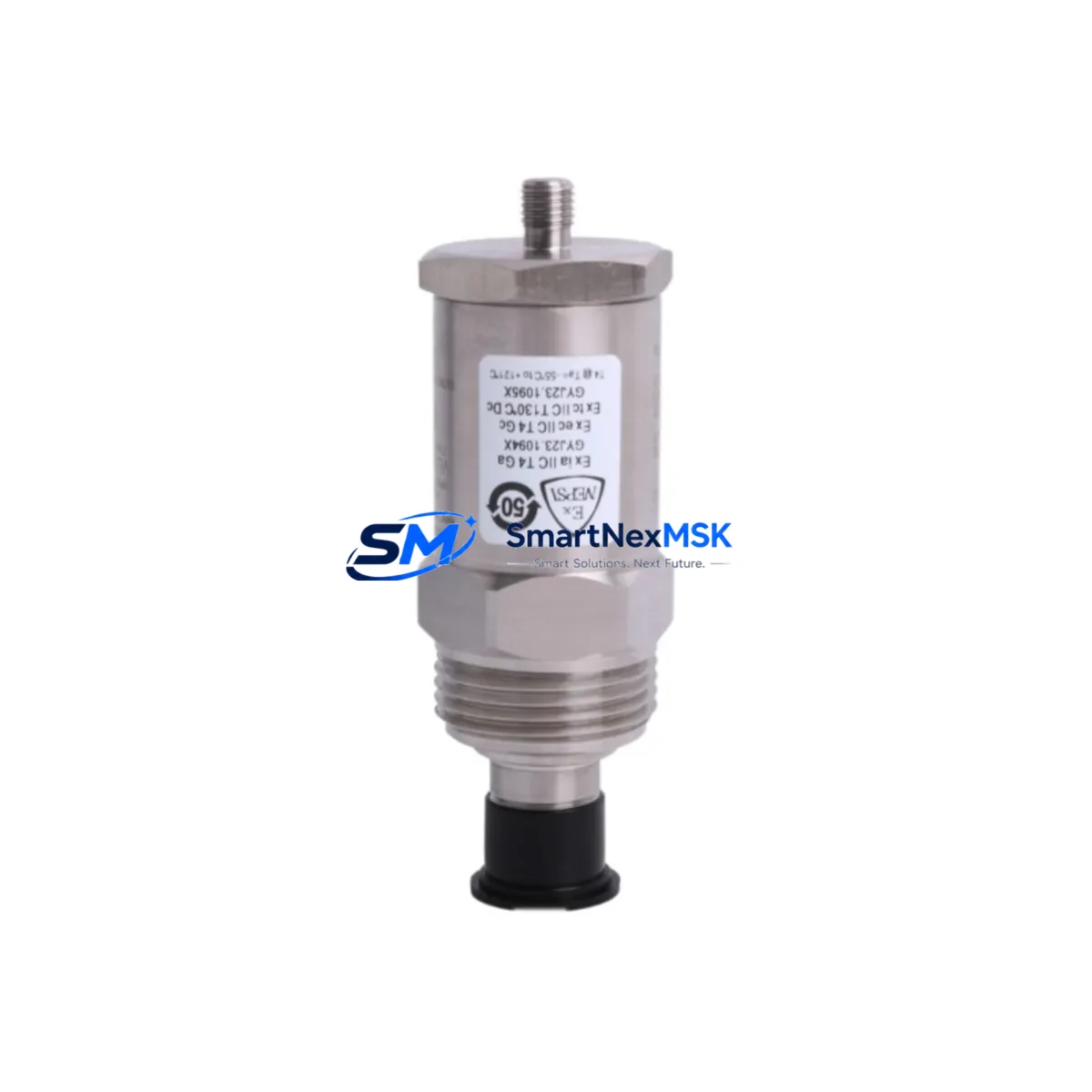
Bently Nevada 190501-12-00-02 Retrofit-Ready Velocity Sensor for 3300/3500 Control Systems
The Bently Nevada 190501-12-00-02 is a Velomitor CT piezoelectric velocity transducer engineered for direct retrofit into legacy Bently Nevada 3300 Series and 3500 Series machinery protection systems. As original Velomitor CT units reach end-of-life or become unavailable through OEM channels, the 190501-12-00-02 provides a verified drop-in replacement path that preserves existing wiring, terminal assignments, and monitor configuration — minimizing engineering rework and unplanned downtime during system modernization.
This transducer delivers a broadband velocity output signal compatible with the 3300/16 Velocity Monitor, 3500/42M Proximitor/Seismic Monitor, and associated I/O modules within the 3500 rack architecture. Its integrated signal conditioning eliminates the need for external barriers or signal converters in most standard installations, making it a preferred choice for maintenance teams executing controlled retrofits on rotating machinery such as compressors, turbines, pumps, and gearboxes.
Upgrade Compatibility Table
| Parameter | Details |
|---|---|
| SKU / Part Number | 190501-12-00-02 |
| OEM Brand | Bently Nevada |
| Compatible Monitor Series | 3300 Series, 3500 Series |
| Compatible Monitors | 3300/16 Velocity Monitor, 3500/42M Proximitor/Seismic Monitor |
| Replaces / Supersedes | Velomitor CT (legacy), 190501-12-00-01 (earlier revision) |
| Output Signal | Velocity (mV/mm/s or mV/in/s, integrated piezoelectric) |
| Mounting Interface | Standard Velomitor CT thread and connector — no adapter required |
| Terminal / Wiring Compatibility | Direct pin-for-pin replacement; existing field cable retained |
| Backplane / Rack Interface | Compatible with 3500 rack backplane I/O termination modules |
| Communication Protocol | Analog 4–20 mA / voltage output; compatible with System 1 software |
| Installation Requirement | Verify torque spec; no firmware change required on 3500/42M |
| Commissioning Note | Confirm transducer OK relay status and alert/danger setpoints post-installation |
| Warranty | 12 Months from shipment date |
| Origin | USA (OEM); SMARTNEXMSK-verified stock |
Retrofit Planning for Existing Automation Systems
A successful retrofit of the 190501-12-00-02 into an operating plant begins well before the maintenance window opens. Engineering teams should first audit the existing 3500 rack configuration, confirming which slots are occupied by the 3500/42M Proximitor/Seismic Monitor and whether the associated 3500/20 Rack Interface Module firmware is current. In many legacy installations, the 3300/16 Velocity Monitor was the original front-end device; migrating to the 3500 platform requires verifying that the I/O termination module — typically a 3500/42-01-00 or equivalent — is correctly wired for the Velomitor CT signal type.
Power budget review is essential. The 3500 rack draws regulated +24 VDC from the 3500/15 Power Supply Module, and adding or replacing transducers changes the aggregate current draw. Confirm that the installed 3500/15 has sufficient headroom before commissioning the replacement 190501-12-00-02. If the rack is near capacity, a second 3500/15 Power Supply Module may be required as a redundant feed.
Terminal block wiring should be documented before disconnection. The Velomitor CT uses a two-wire shielded cable; shield grounding practice at the 3500 I/O termination module must follow Bently Nevada’s single-point grounding guideline to avoid common-mode noise that can trigger false alerts on the 3500/42M. After reconnection, verify continuity and insulation resistance before energizing.
For plants running Bently Nevada System 1 condition monitoring software, the transducer channel configuration — including sensitivity factor, engineering unit scaling, and OK limit thresholds — must be reviewed in the System 1 database. No hardware change to the 3500/42M is required when replacing a like-for-like Velomitor CT, but the channel’s transducer OK relay logic should be re-verified. If the site also uses a 3500/22M Transient Data Interface for startup/shutdown capture, confirm that the new transducer’s sensitivity matches the stored configuration to avoid scaling errors in transient plots.
Plants that have integrated the 3500 rack with a DCS via the 3500/92 Communication Gateway Module (Modbus or Ethernet/IP) should verify that the gateway’s tag mapping remains intact after the transducer swap. No re-mapping is typically needed for a direct replacement, but a communication health check — confirming that the DCS historian is receiving live velocity values — is recommended before returning the machine to service. Similarly, if an HMI faceplate displays real-time velocity trend data sourced from the 3500 rack, operators should confirm that the displayed engineering units and alarm thresholds match the newly installed transducer’s output range.
For sites managing a broader control cabinet upgrade, the 190501-12-00-02 is commonly deployed alongside the 3500/40M Proximitor Monitor for radial vibration, the 3500/45 Position Monitor for axial thrust, and the 3500/50M Tachometer Module for speed and phase reference. Coordinating the replacement of these modules within a single planned outage reduces cumulative downtime and allows a single end-to-end loop check across all channels before restart.
Downtime Control During System Migration
Minimizing production loss during a Velomitor CT replacement requires a structured pre-outage preparation protocol. All replacement components — including the 190501-12-00-02 transducer, spare terminal screws, shielded cable, and any required 3500 I/O termination modules — should be staged and bench-verified before the maintenance window begins. A pre-tested spare reduces the risk of discovering a defective unit after the machine is already offline.
Where process conditions permit, a hot-swap sequence can be planned: the 3500/42M channel is placed in bypass mode via System 1 or the front-panel keyswitch, the legacy Velomitor CT is removed, the 190501-12-00-02 is installed and torqued, and the channel is then re-enabled. This approach keeps the remaining monitoring channels active throughout the swap, preserving protection coverage on adjacent measurement points such as the 3500/40M radial vibration channels.
Original program logic stored in the 3500 rack is non-volatile and is not affected by transducer replacement. However, if the site uses a 3500/22M Transient Data Interface or a 3500/92 Communication Gateway Module, a configuration backup should be exported from System 1 before work begins as a precaution. After installation, a full channel functional test — injecting a known velocity signal at the transducer input and confirming correct readout at the 3500/42M front panel and in System 1 — validates the retrofit before the machine is restarted. Total planned downtime for a single-channel Velomitor CT replacement is typically 2–4 hours when all materials are pre-staged.
Retrofit Support FAQ
Q1: Is the 190501-12-00-02 a direct drop-in replacement for the original Velomitor CT?
Yes. The 190501-12-00-02 uses the same mechanical thread, connector type, and two-wire shielded cable interface as the original Velomitor CT. No adapter plates, cable modifications, or monitor reconfiguration are required for installations on the 3300/16 or 3500/42M. Confirm the transducer sensitivity specification matches the channel configuration in System 1 before re-enabling the channel.
Q2: What commissioning steps are required after installation?
After mechanical installation and wiring reconnection, perform a continuity check on the signal cable, verify shield grounding at the I/O termination module, and confirm the transducer OK relay status on the 3500/42M front panel. Inject a reference signal or perform a bump test to verify that the velocity reading in System 1 matches the expected engineering unit output. Check alert and danger setpoints against the machine’s vibration specification before returning to service.
Q3: Can this transducer be used with legacy 3300 Series monitors as well as the 3500 platform?
Yes. The 190501-12-00-02 is compatible with both the 3300 Series (including the 3300/16 Velocity Monitor) and the 3500 Series (including the 3500/42M). This dual compatibility makes it suitable for phased migration projects where some racks have been upgraded to 3500 while others remain on 3300 hardware.
Q4: What warranty and testing does SMARTNEXMSK provide?
Every 190501-12-00-02 unit shipped by SMARTNEXMSK carries a 12-month warranty from the date of shipment. Prior to dispatch, each unit undergoes functional output verification and visual inspection. Expedited shipping options are available to support urgent maintenance windows. For technical pre-sales support or post-installation troubleshooting, contact our engineering team directly.
© 2026 SMARTNEXMSK. All rights reserved.
Original Source: https://smartnexmsk.com
Contact: [email protected] | +86 18259474341



