
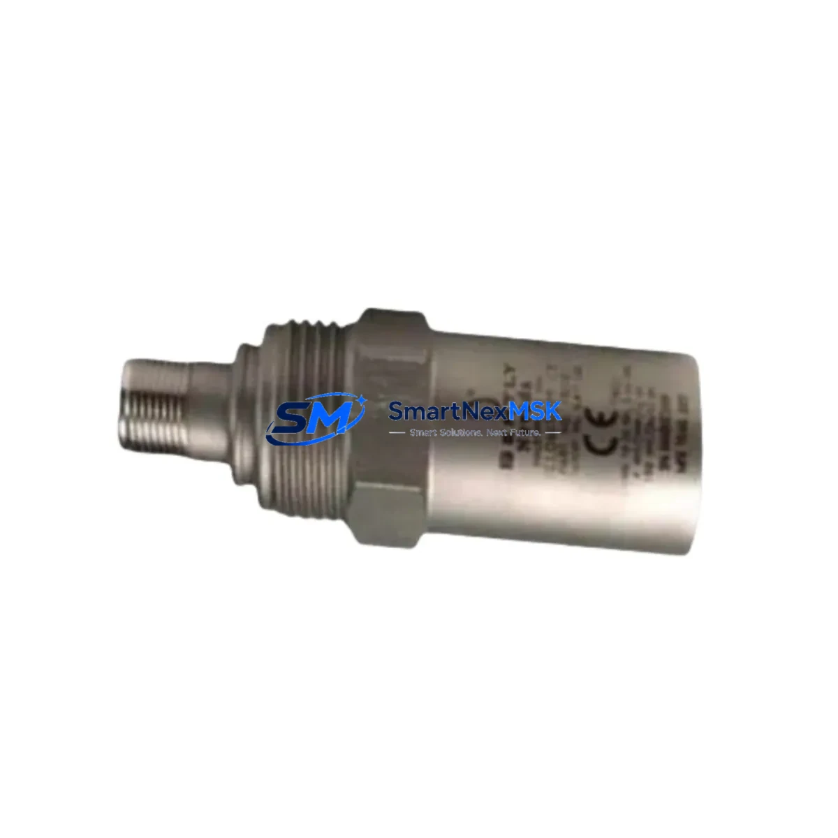
Bently Nevada 190501-14-00-00 Velomitor CT Upgrade: Retrofit-Compatible Velocity Transducer for Legacy Control Systems
The Bently Nevada 190501-14-00-00 Velomitor CT is a high-performance velocity transducer engineered for continuous vibration monitoring in rotating machinery applications. As original Bently Nevada 3300 series installations age and OEM support contracts expire, plant engineers and reliability teams increasingly require a verified, drop-in compatible replacement that preserves existing wiring infrastructure, signal conditioning chains, and DCS/PLC integration without forcing a full system redesign. The 190501-14-00-00 addresses this need directly — offering a retrofit-ready solution for facilities operating legacy turbine protection, compressor monitoring, and pump condition-monitoring systems.
This unit outputs a standard 4–20 mA analog signal compatible with existing Bently Nevada 3500 series rack-mounted monitors, including the 3500/42M Proximitor/Seismic Monitor and the 3500/46M Hydro Monitor. Engineers migrating from earlier 3300/20 Proximitor systems will find that the 190501-14-00-00 maintains the same terminal block pinout convention, reducing rewiring time during scheduled maintenance windows. The transducer’s integral cable assembly is rated for industrial environments and is compatible with standard Bently Nevada armored extension cables used throughout the 3300 and 3500 platform families.
Upgrade Compatibility Table
| Parameter | 190501-14-00-00 (This Unit) | Legacy / Replaced Models |
|---|---|---|
| Output Signal | 4–20 mA analog | 4–20 mA analog (3300/20 compatible) |
| Mounting Interface | Standard Velomitor CT housing, M8 thread | Same — direct mechanical replacement |
| Compatible Monitors | 3500/42M, 3500/46M, 3500/40M | 3300/20, 3300/25, 3300/55 |
| Communication Protocol | Analog 4–20 mA (passive loop) | Analog 4–20 mA — no protocol migration required |
| Terminal Wiring | 2-wire loop-powered, standard Bently Nevada color code | Compatible — no rewiring required in most installations |
| Backplane / Rack Interface | External field-mount; connects to 3500 I/O module terminal block | Same rack slot — no rack modification needed |
| Commissioning Requirement | Verify OK relay setpoints and full-scale calibration in System 1 software | Re-use existing calibration records as baseline |
| Warranty | 12-Month Warranty — covers manufacturing defects and functional failure under normal operating conditions | |
Retrofit Planning for Existing Automation Systems
Successful integration of the 190501-14-00-00 into a running plant begins well before the physical swap. Reliability engineers should first audit the existing 3500 rack configuration to confirm that the target channel on the 3500/42M or 3500/40M Proximitor/Seismic Monitor is configured for velocity input rather than proximity (eddy-current) mode. This distinction is critical: a channel configured for a proximity probe will not correctly interpret the Velomitor CT’s 4–20 mA velocity signal, and incorrect alarm setpoints could mask real machinery faults or generate nuisance trips.
Next, verify the power supply capacity of the 3500 rack’s internal power module — typically the 3500/15 Power Supply or the 3500/15LF Low-Frequency variant. Each active transducer channel draws loop current from the rack’s 24 VDC bus, and adding replacement transducers to previously unused channels can push total draw close to the module’s rated output. Where power budget is tight, consider whether the 3500/05 System Rack or a secondary 3500/15 can be added to distribute load before the retrofit window opens.
Terminal block wiring should be documented with as-found photographs before any disconnection. The 190501-14-00-00 uses the same two-wire loop-powered architecture as the original Velomitor CT family, so existing field cable runs — including any Bently Nevada armored extension cables terminated at the junction box — can typically be reused without modification. Confirm cable insulation resistance with a 500 V megger test before reconnection, particularly in installations where cables pass through high-temperature zones near turbine casings.
For facilities running Bently Nevada System 1 condition monitoring software, the transducer replacement does not require a new device driver or database record — the existing measurement point configuration remains valid provided the sensitivity value (mV/mm/s or mV/in/s) matches the replacement unit’s specification. Cross-reference the 190501-14-00-00 datasheet sensitivity against the value stored in the System 1 point configuration before closing out the work order. If the plant also operates a Rockwell Automation ControlLogix or CompactLogix PLC reading the 3500 rack’s Modbus TCP gateway output, confirm that the PLC’s analog input scaling block reflects the correct engineering unit range — a mismatch here will cause incorrect velocity readings on the HMI faceplate without triggering any hardware fault.
Plants migrating from older 3300 series racks to the 3500 platform as part of a broader control system upgrade should also plan for I/O module address reassignment. The 3500/20 Rack Interface Module assigns channel addresses sequentially from slot position, so any change in rack population — such as adding a 3500/22M Transient Data Interface or a 3500/32 4-Channel Relay Module — will shift downstream channel addresses and require corresponding updates in the DCS tag database and HMI graphic displays.
Downtime Control During System Migration
Minimizing unplanned downtime during a Velomitor CT replacement requires a structured hot-swap protocol. Where the process unit can be kept running at reduced load, the preferred approach is to bypass the affected monitor channel in the 3500 rack’s configuration software, install the 190501-14-00-00, verify loop continuity and signal level, then re-enable the channel and confirm alarm setpoints before returning the channel to normal protection mode. This sequence keeps the machinery online and the remaining protection channels active throughout the swap.
For installations where the 3500 rack is the sole protection system and a full bypass is not permissible under site safety rules, coordinate with the control room to place the affected unit in manual control via the DCS — typically a Honeywell Experion PKS, Emerson DeltaV, or ABB 800xA system — before isolating the transducer loop. Ensure the DCS operator has a pre-agreed response procedure for the duration of the bypass window. Document the bypass start and end times in the site’s management-of-change (MOC) log.
After physical installation, perform a bump test by applying a calibrated vibration source to the transducer mounting surface and confirming that the 3500 monitor channel displays the expected velocity value within ±2% of the reference. Cross-check the reading against the System 1 trend display and the DCS historian tag to confirm end-to-end signal integrity before signing off the work order. All units supplied by SMARTNEXMSK are pre-tested prior to shipment and include a factory test report, reducing the risk of commissioning delays caused by out-of-tolerance units.
Retrofit Support FAQ
Q1: Is the 190501-14-00-00 a direct drop-in replacement for the original Bently Nevada Velomitor CT, and will it work with my existing 3500/42M monitor?
Yes. The 190501-14-00-00 is mechanically and electrically compatible with the original Velomitor CT form factor. It connects to the 3500/42M terminal block using the same two-wire loop-powered wiring scheme. No hardware modifications to the monitor or rack are required. Confirm the channel is configured for velocity (not proximity) input in the 3500 rack configuration software before installation.
Q2: What wiring checks should I perform before connecting the replacement transducer?
Before reconnecting the field cable, perform a continuity check on both conductors and a 500 V insulation resistance test between each conductor and cable shield. Verify that the junction box terminal screws are torqued to the manufacturer’s specification and that the cable shield is grounded at one end only (typically at the rack end) to avoid ground loops that can introduce noise into the 4–20 mA signal.
Q3: Do I need to recalibrate the 3500 monitor or update System 1 after installing the 190501-14-00-00?
In most cases, no full recalibration is required. Verify that the sensitivity value in the System 1 measurement point configuration matches the 190501-14-00-00 datasheet specification. If the values match, the existing alarm setpoints and trend baselines remain valid. Perform a functional check by applying a known vibration input and confirming the displayed value is within the acceptable tolerance band before returning the channel to protection service.
Q4: What does the 12-month warranty cover, and what is the process for a warranty claim?
The 12-month warranty covers manufacturing defects and functional failure under normal operating conditions from the date of shipment. It does not cover damage caused by incorrect installation, overvoltage, mechanical impact, or operation outside the rated environmental specifications. To initiate a warranty claim, contact SMARTNEXMSK with the original order number, a description of the failure mode, and photographs of the installation. Replacement units are dispatched after fault verification, with priority handling for critical plant applications.
© 2026 SMARTNEXMSK. All rights reserved.
Original Source: https://smartnexmsk.com
Contact: [email protected] | +86 18259474341



