
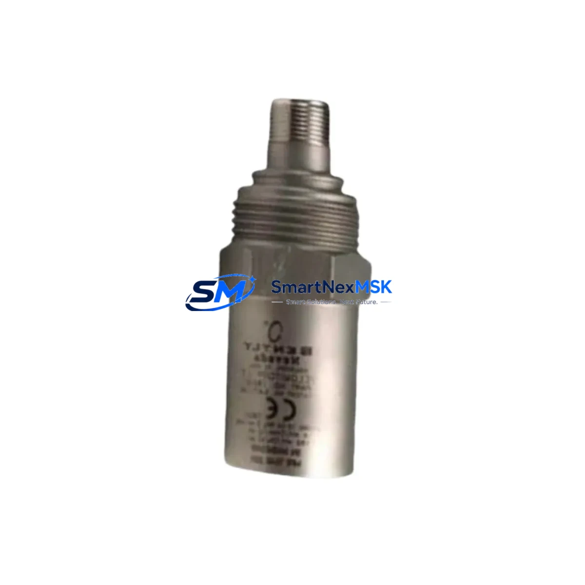
Bently Nevada 190501-14-99-01 Maintenance-Ready Spare for Velomitor CT Automation
The Bently Nevada 190501-14-99-01 is a Velomitor CT piezoelectric velocity transducer engineered for continuous vibration monitoring in rotating machinery applications. As a maintenance-ready original spare, this unit is designed to support rapid field replacement in turbines, compressors, pumps, motors, and gearboxes where unplanned downtime carries significant operational and financial risk. Sourced directly from authorized supply channels, each unit undergoes pre-shipment functional verification to confirm output sensitivity, frequency response, and connector integrity before dispatch.
For maintenance engineers managing aging machinery protection systems, the 190501-14-99-01 represents a direct, pin-compatible replacement for worn or failed Velomitor CT transducers without requiring reconfiguration of the monitoring rack or signal conditioning chain. Its 4-pin MIL-C-5015 connector and standard 100 mV/in/s sensitivity make it interchangeable within existing Bently Nevada 3500 Series and 7200 Series monitoring frameworks, preserving alarm setpoints and trend baselines accumulated over years of operation.
Procurement engineers sourcing this unit for planned maintenance shutdowns or emergency stock replenishment can rely on a 12-month warranty covering manufacturing defects, with documented test records available upon request. Long-term supply continuity is supported through established distributor relationships, ensuring availability even for legacy system configurations that have been discontinued from the OEM’s active catalog.
Spare Maintenance Table
| Parameter | Specification |
|---|---|
| Part Number | 190501-14-99-01 |
| Brand | Bently Nevada |
| Series | Velomitor CT |
| Transducer Type | Piezoelectric Velocity Transducer |
| Sensitivity | 100 mV/in/s (4 mV/mm/s) |
| Frequency Range | 2 Hz – 1,000 Hz (±3 dB) |
| Operating Temperature | -40°C to +121°C |
| Connector Type | 4-Pin MIL-C-5015 |
| Housing Material | 316 Stainless Steel |
| Mounting | 1/4-28 UNF Stud Mount |
| Compatibility | Bently Nevada 3500 Series, 7200 Series Monitoring Systems |
| Application | Turbines, Compressors, Pumps, Motors, Gearboxes |
| Origin | USA |
| Warranty | 12 Months |
| Condition | Original Spare, Pre-shipment Tested |
Maintenance Planning for Continuous Operation
When replacing the 190501-14-99-01 Velomitor CT transducer during a planned or emergency maintenance event, a thorough inspection of the surrounding signal chain is essential to prevent repeat failures and ensure measurement integrity after recommissioning. Maintenance engineers should begin by verifying the condition of the Bently Nevada 3500/42M Velocity Monitor module, which processes the transducer’s analog output — a degraded input card can mask a healthy transducer or generate false alarms even after a successful sensor swap.
The interconnecting cable assembly between the transducer and the monitor rack deserves close attention. Velomitor CT installations typically use shielded, low-capacitance instrument cable; any cable showing insulation cracking, moisture ingress at the conduit entry, or shield continuity loss should be replaced concurrently. Connector pins on the MIL-C-5015 field connector should be inspected for corrosion, fretting, or mechanical damage before mating with the new transducer.
Within the same control cabinet, engineers should audit the 3500 Series rack power supply module — typically the 3500/15 Power Supply — for output voltage stability, since transient supply fluctuations can corrupt velocity trend data and trigger nuisance trips. The 3500/01 Rack Interface Module (RIM) and its communication link to the DCS or SCADA historian should also be confirmed operational, as a failed RIM will prevent alarm acknowledgment and data logging even when the transducer itself is functioning correctly.
For installations where the Velomitor CT feeds into a Bently Nevada System 1 condition monitoring platform, the I/O module mapping and channel configuration should be verified post-replacement to ensure the new transducer’s serial number and calibration data are correctly registered. If the machinery protection system interfaces with a Rockwell Automation ControlLogix or Siemens S7-300/400 PLC via Modbus or Profibus, the communication module and associated terminal blocks should be checked for loose connections that may have developed during the vibration events that precipitated the transducer failure.
Signal isolators or barriers installed between the transducer output and the monitor input — particularly in hazardous area installations requiring ATEX or IECEx compliance — should be tested for correct pass-through gain and frequency response after the transducer swap. Fuse holders and protection relays in the machinery protection loop should be inspected and fuse ratings confirmed against the circuit design documentation.
Site Replacement Workflow
Step 1 — Pre-replacement verification: Confirm the failed unit’s part number against the maintenance record. Cross-reference 190501-14-99-01 against the installed base list to identify any superseding Bently Nevada part numbers (e.g., 190501-14-99-02 or later revisions) that may have been issued since original installation. Confirm physical mounting thread, connector type, and cable length requirements before ordering.
Step 2 — Safe isolation: Follow site LOTO (Lockout/Tagout) procedures. Isolate the monitor channel at the 3500 rack before disconnecting the transducer to prevent false trip signals from propagating to the machinery protection relay output.
Step 3 — Physical replacement: Remove the failed 190501-14-99-01 using the correct torque specification for the 1/4-28 UNF stud mount. Clean the mounting surface and apply anti-seize compound if required by site standards. Install the replacement unit and torque to specification. Reconnect the field cable, ensuring the shield drain wire is correctly terminated at the single-point ground.
Step 4 — Functional verification: With the monitor channel re-enabled, confirm the transducer output is within the expected quiescent voltage range (typically 8–12 VDC bias for Velomitor CT). Perform a bump test or use a calibrated vibration reference source to verify sensitivity and frequency response before returning the machinery to service.
Step 5 — Documentation and stock replenishment: Update the CMMS (Computerized Maintenance Management System) with the replacement date, new unit serial number, and test results. Initiate a purchase order to replenish the consumed spare, maintaining a minimum stock level of one unit per critical machine train.
Spare Parts Support FAQ
Q: Is the 190501-14-99-01 a direct drop-in replacement for older Velomitor CT units installed in the 1990s and 2000s?
A: Yes. The 190501-14-99-01 maintains the same mechanical interface (1/4-28 UNF stud), connector type (4-pin MIL-C-5015), and electrical output (100 mV/in/s) as earlier production runs. No reconfiguration of the 3500 Series monitor is required. Verify the cable assembly connector is compatible before installation.
Q: What pre-shipment testing is performed on each unit?
A: Each 190501-14-99-01 is functionally tested for output sensitivity, frequency response linearity, and connector integrity prior to dispatch. Test documentation is available upon request for quality assurance records.
Q: How should this spare be stored if not immediately installed?
A: Store in the original packaging in a dry, temperature-controlled environment (0°C to +60°C) away from strong magnetic fields and mechanical shock. Inspect the connector protective cap before long-term storage. Recommended maximum shelf storage before installation verification: 24 months.
Q: What is covered under the 12-month warranty?
A: The 12-month warranty covers manufacturing defects in materials and workmanship from the date of shipment. It does not cover damage resulting from incorrect installation, overvoltage, mechanical impact, or operation outside the specified environmental limits. Warranty claims are processed with return of the defective unit and supporting installation documentation.
© 2026 SMARTNEXMSK. All rights reserved.
Original Source: https://smartnexmsk.com
Contact: [email protected] | +86 18259474341



