
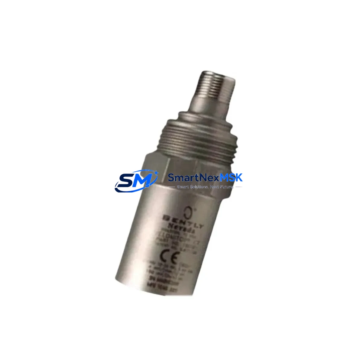
Bently Nevada 190501-16-00-00 Spare Velomitor CT: Spare Replacement for Rotating Machinery Condition Monitoring
The Bently Nevada 190501-16-00-00 Velomitor CT is a piezoelectric velocity transducer engineered for continuous vibration monitoring on rotating machinery in oil & gas, power generation, petrochemical, and heavy industrial environments. When a velocity transducer fails or degrades, the consequences extend beyond a single sensor — unmonitored shaft vibration can escalate to bearing failure, seal damage, and unplanned shutdown events that cost thousands per hour. Stocking a verified original spare of the 190501-16-00-00 is a fundamental element of any proactive maintenance strategy for Bently Nevada-equipped machinery trains.
This unit is sourced as an original Bently Nevada component, fully tested prior to shipment, and backed by a 12-month warranty. It is compatible with Bently Nevada 3500 Series machinery protection system racks and integrates directly with existing field wiring and junction boxes without modification. Maintenance engineers can execute a like-for-like replacement during a planned outage window or emergency shutdown, restoring full vibration monitoring capability with minimal downtime.
Spare Maintenance Table
| Parameter | Specification |
|---|---|
| Part Number / SKU | 190501-16-00-00 |
| Brand | Bently Nevada |
| Series | Velomitor CT |
| Product Type | Piezoelectric Velocity Transducer |
| Measurement Type | Casing / Bearing Housing Vibration Velocity |
| Output Signal | Velocity (mV/mm/s or mV/in/s, per configuration) |
| Compatible Monitor | Bently Nevada 3500 Series Machinery Protection System |
| Mounting | Stud mount, standard industrial thread |
| Cable / Connector | Integral cable with MIL-spec connector |
| Operating Temperature | -40°C to +121°C (typical industrial range) |
| Application Environment | Rotating machinery: turbines, compressors, pumps, motors, fans |
| Compatibility | Direct replacement for 190501-16-00-00; compatible with existing 3500 rack I/O modules |
| Installation | Like-for-like field replacement; no rack reconfiguration required |
| Condition | Original spare, factory-tested |
| Warranty | 12 Months |
| Lead Time | In-stock; ships within 1–3 business days |
| Origin | USA |
Maintenance Planning for Continuous Operation
Replacing the 190501-16-00-00 Velomitor CT in the field is rarely an isolated task. A thorough maintenance engineer will treat the transducer swap as an opportunity to inspect the entire vibration monitoring loop and adjacent protection circuits. Before returning the machine to service, the following components and subsystems should be verified:
Begin with the Bently Nevada 3500/42M Velocity Monitor module seated in the 3500 rack — confirm the channel configuration, OK relay status, and alarm setpoints have not drifted. Inspect the 3500/20 Rack Interface Module (RIM) for communication integrity with the DCS or safety system. Check the field junction box and terminal strips for moisture ingress, corrosion, or loose terminations that may have contributed to the original transducer fault.
Examine the transducer extension cable (typically a Bently Nevada 330130 or equivalent armored cable) for jacket damage, kinking near the connector, or continuity loss — cable degradation is a common root cause of apparent transducer failures. Verify the barrier or signal conditioner in the intrinsically safe circuit, if applicable, as a failed zener barrier can damage replacement transducers within hours of reinstallation.
For machines running in parallel trains, cross-check the companion Bently Nevada 330400 proximity probe and driver on the same shaft to ensure radial vibration data remains consistent with the velocity reading. If the control cabinet houses a 3500/15 Power Supply Module, verify output voltage stability — undervoltage conditions are a silent cause of transducer signal anomalies. Review the 3500/92 Communication Gateway Module if the rack feeds Modbus or OPC data to a SCADA or historian, ensuring the channel mapping is intact after any rack disturbance.
Finally, inspect the grounding and shielding continuity of the entire transducer loop back to the rack chassis. Poor shield grounding introduces noise that can trigger nuisance alarms or mask real vibration events. Document all findings in the maintenance management system before closing the work order.
Site Replacement Workflow
Step 1 — Isolation & Permit: Obtain a work permit and isolate the monitoring channel at the 3500 rack. Place the affected channel in bypass mode to prevent spurious trips during the replacement procedure.
Step 2 — Transducer Removal: Disconnect the integral cable connector at the junction box. Unscrew the 190501-16-00-00 from the mounting stud, noting the orientation if directional mounting is required by the OEM specification.
Step 3 — Inspection: Inspect the mounting surface for corrosion, thread damage, or contamination. Clean the stud and apply anti-seize compound if specified. Inspect the mating connector and cable for damage before installing the replacement unit.
Step 4 — Installation: Thread the replacement 190501-16-00-00 onto the stud to the specified torque. Reconnect the cable at the junction box, ensuring the connector is fully seated and the locking ring is engaged.
Step 5 — Loop Check & Commissioning: Remove the bypass at the 3500 rack. Verify the OK LED illuminates on the 3500/42M module. Confirm live vibration readings are within expected baseline range before returning the machine to normal operation. Log the replacement in the CMMS with the new unit serial number and installation date.
This workflow minimizes downtime, maintains system compatibility, and ensures the replacement is fully commissioned before the machine is released — a critical discipline for high-availability rotating equipment.
Spare Parts Support FAQ
Q1: Is the 190501-16-00-00 a direct drop-in replacement for the existing unit?
Yes. The 190501-16-00-00 is a like-for-like replacement. It uses the same mounting thread, connector type, and signal output as the original, requiring no changes to the 3500 rack configuration, field wiring, or alarm setpoints.
Q2: How is the unit tested before shipment?
Each 190501-16-00-00 unit undergoes functional verification prior to dispatch, including output signal check and connector integrity inspection. A test report is available upon request. The unit ships with a 12-month warranty covering manufacturing defects and functional failure under normal operating conditions.
Q3: What is the recommended spare parts inventory strategy for this transducer?
For critical rotating machinery, industry best practice recommends holding a minimum of one spare 190501-16-00-00 per monitored machine train, with an additional buffer unit for facilities operating multiple identical trains. Given the lead times associated with OEM procurement, maintaining an on-hand spare eliminates the risk of extended downtime while awaiting delivery.
Q4: Can this unit be used on machines not currently monitored by a Bently Nevada 3500 system?
The 190501-16-00-00 Velomitor CT is optimized for integration with Bently Nevada 3500 Series monitors. While the piezoelectric output is compatible with other velocity monitor inputs in principle, compatibility verification against the target monitor’s input impedance and signal conditioning requirements is recommended before installation in a non-Bently Nevada system.
© 2026 SMARTNEXMSK. All rights reserved.
Original Source: https://smartnexmsk.com
Contact: [email protected] | +86 18259474341



