
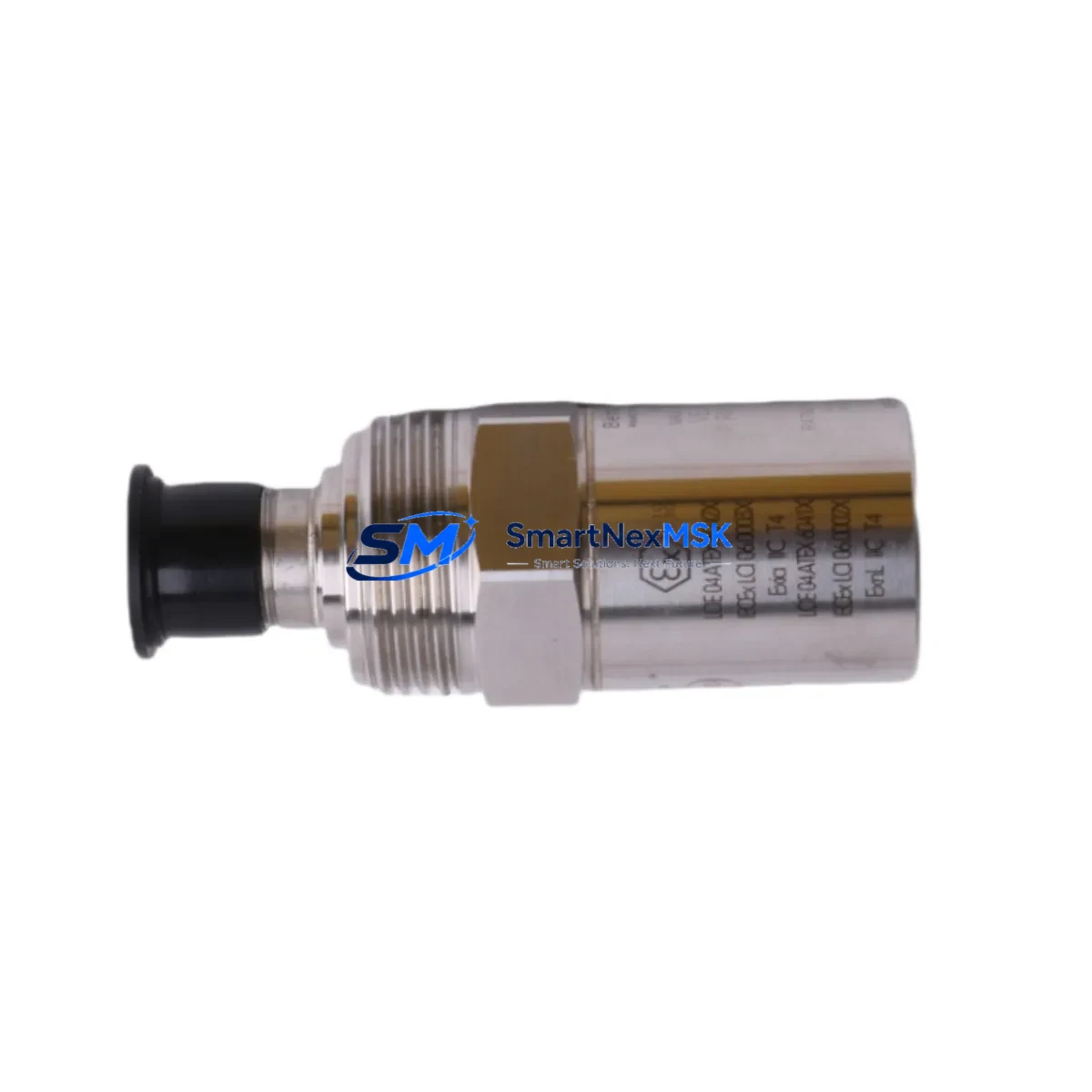
Bently Nevada 190501-16-00-CN Spare for Velomitor CT Automation: Spare Replacement & Industrial Downtime Risk Control
The Bently Nevada 190501-16-00-CN is an original Velomitor CT piezo-velocity transducer engineered for continuous vibration monitoring in rotating machinery protection systems. Designed to integrate directly with the Bently Nevada 3500 Series machinery protection system, this transducer delivers reliable velocity output across a broad frequency range, making it a critical spare component for maintenance engineers managing turbines, compressors, pumps, and motors in process-critical environments.
For maintenance and procurement engineers, having a verified, tested replacement unit of the 190501-16-00-CN on the shelf is not optional — it is a fundamental element of any serious predictive maintenance or emergency response plan. Unplanned downtime caused by a failed velocity transducer can cascade into extended outages, missed production targets, and costly emergency procurement at premium prices. Stocking this spare eliminates that risk.
This unit ships fully tested, with original specifications verified prior to dispatch. Each unit carries a 12-month warranty covering manufacturing defects and functional performance, giving procurement teams the confidence to approve purchase orders without extended qualification cycles.
Spare Maintenance Table
| Parameter | Specification |
|---|---|
| Part Number | 190501-16-00-CN |
| Brand | Bently Nevada |
| Series | Velomitor CT (Piezo-Velocity Transducer) |
| Compatible System | Bently Nevada 3500 Series Machinery Protection |
| Output Signal | Velocity (mV/mm/s or mV/in/s) |
| Frequency Range | Approx. 2 Hz – 2,000 Hz |
| Connector Type | MIL-C-5015 style (per CN variant) |
| Housing | Stainless steel, IP67-rated |
| Application | Turbines, compressors, pumps, motors, fans |
| Installation | Threaded stud mount, radial or axial orientation |
| Operating Temperature | -40°C to +121°C |
| Origin | USA (Original Bently Nevada) |
| Warranty | 12 Months |
| Condition | New / Surplus New |
| Lead Time | In stock — ships within 1–3 business days |
Maintenance Planning for Continuous Operation
When a 190501-16-00-CN Velomitor CT transducer is flagged for replacement during a scheduled outage or emergency shutdown, experienced maintenance engineers know that the transducer itself is rarely the only component that requires attention. A thorough inspection of the surrounding measurement chain and control cabinet is essential to restore full system integrity and prevent repeat failures.
Begin by inspecting the Bently Nevada 3500/42M Velocity Monitor module, which processes the signal from the 190501-16-00-CN. If the transducer has been operating in a high-vibration or high-temperature environment, the monitor card may show drift or calibration offset that requires correction or replacement. Alongside this, check the 3500/20 Rack Interface Module (RIM) for communication faults and verify that the rack backplane connections are secure and free of corrosion.
The interconnect cable assembly between the transducer and the monitor rack is a frequent failure point — inspect for chafing, connector pin corrosion, and shield continuity. Replacement cables compatible with the CN connector variant should be kept as part of the standard spare kit. Similarly, review the junction box terminal blocks and field wiring for insulation breakdown, especially in high-temperature zones near turbine casings.
For systems where the 190501-16-00-CN feeds into a Bently Nevada 3500/22M Transient Data Interface or a System 1 condition monitoring platform, verify that the software configuration reflects the correct transducer sensitivity and engineering unit scaling after replacement. Misconfigured sensitivity values are a common post-replacement error that can trigger false alarms or mask real vibration events.
In control cabinets housing the 3500 rack, also inspect the 3500/15 Power Supply module for output voltage stability — a degraded power supply can cause erratic transducer readings that mimic sensor failure. If the system includes Keyphasor transducers (such as the 330180 series) for phase reference, verify their gap voltage and signal quality as part of the same maintenance window.
For older installations where the 190501-16-00-CN is part of a legacy monitoring loop, consider also reviewing any signal conditioners or isolators in the measurement chain, as well as surge protection devices at the field junction. These components degrade silently and are often overlooked until a second failure occurs shortly after the primary repair.
Procurement engineers should note that maintaining a minimum stock of two 190501-16-00-CN units, alongside compatible 3500 series monitor cards and interconnect cable assemblies, is the industry-standard approach for critical rotating machinery protection systems. This ensures that any emergency replacement can be completed within a single shift without waiting for international freight.
Site Replacement Workflow
Step 1 — Isolation and Lockout: Follow site LOTO procedures. Isolate the 3500 rack channel associated with the 190501-16-00-CN. Bypass the channel in System 1 or the DCS to prevent spurious trips during replacement.
Step 2 — Transducer Removal: Disconnect the field cable at the junction box or directly at the transducer connector. Note the mounting orientation (radial or axial) and the stud torque specification before removal. Clean the mounting surface and inspect for thread damage.
Step 3 — Incoming Inspection: Before installing the replacement 190501-16-00-CN, verify the part number label, connector type (CN variant), and cable length match the original. Perform a bench check of output impedance if test equipment is available.
Step 4 — Installation: Mount the replacement transducer to the specified torque. Reconnect the field cable, ensuring the connector is fully seated and the locking ring is engaged. Restore field wiring at the junction box and verify shield grounding.
Step 5 — Commissioning: Restore power to the 3500 rack channel. Verify the gap voltage or bias voltage reading at the monitor module is within the acceptable range for the Velomitor CT. Confirm that vibration readings are stable and consistent with adjacent measurement points before removing the bypass.
Step 6 — Documentation: Record the replacement in the maintenance management system (CMMS), including the new unit serial number, installation date, and post-replacement readings. Update the spare parts inventory to trigger reorder of the consumed unit.
Spare Parts Support FAQ
Q1: Is the 190501-16-00-CN a direct drop-in replacement for earlier Velomitor CT variants?
The 190501-16-00-CN is the CN-connector variant of the Velomitor CT family. It is dimensionally and electrically compatible with other 190501 series variants in the same connector configuration. If your existing installation uses a different connector suffix, verify the connector type before ordering. Our technical team can assist with cross-reference confirmation prior to shipment.
Q2: How is each unit tested before shipment?
Every 190501-16-00-CN unit undergoes functional verification prior to dispatch, including output signal check and connector integrity inspection. Units are shipped with protective packaging to prevent transit damage. A test report is available upon request for critical applications.
Q3: What does the 12-month warranty cover?
The 12-month warranty covers manufacturing defects and functional performance failures under normal operating conditions. It does not cover damage resulting from incorrect installation, overvoltage, or mechanical impact. Warranty claims are processed with priority turnaround to minimize your downtime exposure.
Q4: Can you support long-term or blanket purchase orders for this part?
Yes. For maintenance teams managing multiple 3500 series installations or planning annual outage schedules, we support blanket PO arrangements with reserved stock allocation. Contact our sales team to discuss volume pricing, lead time guarantees, and consignment stocking options tailored to your maintenance cycle.
© 2026 SMARTNEXMSK. All rights reserved.
Original Source: https://smartnexmsk.com
Contact: [email protected] | +86 18259474341



