
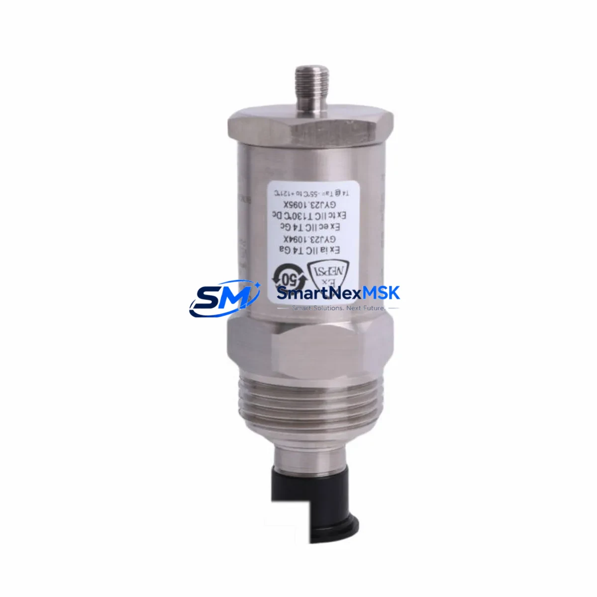
Bently Nevada 190501-19-00-04 Retrofit-Ready Velocity Transducer for 3300 Series Control Systems
The Bently Nevada 190501-19-00-04 Velomitor CT is a high-performance velocity transducer engineered for direct retrofit into existing Bently Nevada 3300 Series vibration monitoring systems. As legacy machinery protection infrastructure ages and OEM support windows close, plant engineers and reliability teams increasingly require a verified drop-in replacement that preserves signal integrity, maintains rack compatibility, and eliminates the need for panel rewiring or software reconfiguration. The 190501-19-00-04 meets all of these requirements, making it the preferred choice for brownfield upgrades, emergency spare replenishment, and planned system modernization projects.
This transducer is designed to interface directly with the Bently Nevada 3300/16 and 3300/20 monitor modules without modification to existing terminal block wiring. The standard 2-pin MIL-spec connector and 4–20 mA output signal are fully compatible with the signal conditioning inputs on the 3300 XY/16 and 3300 XY/20 monitor cards. Engineers replacing a failed or end-of-life unit can complete the swap without altering the Keyphasor reference signal routing or reconfiguring the 3500/42M proximity monitor settings, significantly reducing commissioning time during planned or unplanned outages.
Upgrade Compatibility Table
| Parameter | 190501-19-00-04 (This Unit) | Notes / Retrofit Guidance |
|---|---|---|
| Replaces / Supersedes | 190501-19-00-01, 190501-19-00-02 | Direct drop-in; no wiring change required |
| Compatible Monitor Series | Bently Nevada 3300, 3500 | Verify slot address on 3500/42M or 3300/16 |
| Output Signal | 4–20 mA velocity | Matches legacy signal conditioning inputs |
| Connector Type | 2-pin MIL-spec | Reuse existing field cable; no re-termination |
| Frequency Range | 2–1000 Hz | Covers low-speed and high-speed machinery |
| Installation | Stud-mount, radial or axial | Confirm mounting orientation matches original |
| Communication Compatibility | Analog (4–20 mA); System 1 software compatible | No protocol migration required |
| Commissioning Focus | Zero-speed check, full-speed vibration baseline | Compare to historical trend data in System 1 |
| Warranty | 12 Months | Covers manufacturing defects; includes test report |
Retrofit Planning for Existing Automation Systems
Successful integration of the 190501-19-00-04 into a running plant begins well before the physical swap. Reliability engineers should first pull the existing vibration trend data from the Bently Nevada System 1 condition monitoring software to establish a pre-replacement baseline. This baseline will serve as the acceptance criterion during post-installation commissioning and helps distinguish normal machinery behavior from installation anomalies.
Before removing the legacy transducer, verify the power supply capacity of the existing 3300 Series rack. The 3300/05 power supply module typically provides sufficient headroom for a single transducer replacement, but aging racks with multiple simultaneous upgrades — such as adding a 3300/16 dual-channel monitor card alongside the transducer swap — should be load-checked against the rack’s rated output. If the rack is also hosting a 3300 Keyphasor module for phase reference, confirm that the Keyphasor signal is not interrupted during the transducer replacement, as loss of phase reference will affect all synchronous vibration measurements in the rack.
Terminal block wiring should be documented with photographs before disconnection. The 190501-19-00-04 uses the same pinout as its predecessors, so the existing field cable can be reused without re-termination. However, if the field cable shows signs of insulation degradation — common in high-temperature environments near steam turbines or compressor trains — replacement with a shielded twisted-pair cable rated for the ambient temperature is strongly recommended. Verify that the cable shield is grounded at one end only to prevent ground loops that can introduce noise into the 4–20 mA signal path.
For plants running a DCS backbone — such as a Honeywell Experion PKS or Emerson DeltaV system — the 4–20 mA output from the 190501-19-00-04 typically feeds into an analog input module on the DCS I/O rack. Confirm that the AI module’s input range is configured for 4–20 mA and that the engineering unit scaling in the DCS tag database matches the transducer’s sensitivity specification. If the DCS historian is logging vibration data, verify that the tag alias is correctly mapped after the replacement to avoid data gaps in the long-term trend record.
In control cabinets where the 3300 Series rack shares space with a PLC — such as an Allen-Bradley ControlLogix or Siemens S7-300 — ensure that the vibration alarm outputs from the 3300 monitor cards are correctly wired to the PLC’s digital input module. These hardwired alarm signals are independent of the Modbus or Ethernet/IP communication link between the 3300 rack and the plant DCS, and they must be verified separately during commissioning. A simple loop test using a 4–20 mA calibrator connected at the transducer terminal block will confirm end-to-end signal integrity before the machine is returned to service.
Downtime Control During System Migration
Minimizing production impact during a transducer replacement requires a structured pre-outage preparation plan. All replacement components — including the 190501-19-00-04 transducer, spare terminal screws, cable glands, and a calibrated 4–20 mA loop calibrator — should be staged and verified before the maintenance window opens. A pre-written commissioning checklist covering power-up sequence, zero-speed signal check, full-speed vibration baseline comparison, and alarm setpoint verification will allow the maintenance team to complete the replacement and return the machine to service within a single shift.
Where the plant’s safety instrumented system (SIS) monitors the same measurement point, coordinate with the SIS engineer to place the relevant SIS loop in bypass mode for the duration of the replacement. Document the bypass activation and restoration in the plant’s management of change (MOC) system. Once the 190501-19-00-04 is installed and the vibration signal is confirmed stable in System 1, restore the SIS loop and verify that the SIS logic controller — whether a Triconex Tricon or a Rockwell GuardLogix — correctly receives the restored analog input before closing the work order.
Retaining the original program logic in the PLC or DCS controller is a key advantage of this drop-in replacement. Because the 190501-19-00-04 maintains the same output signal range and connector interface as the units it replaces, no changes to ladder logic, function block diagrams, or HMI faceplate configurations are required. Operators monitoring the machine from an iFIX or Wonderware InTouch HMI will see continuous, uninterrupted data throughout the replacement process, provided the machine remains in operation or the HMI is configured to display the last known value during the brief signal interruption at the moment of transducer swap.
Retrofit Support FAQ
Q: Is the 190501-19-00-04 a direct replacement for the 190501-19-00-01 and 190501-19-00-02?
A: Yes. The 190501-19-00-04 is the current production revision and is a verified drop-in replacement for both earlier suffix variants. No wiring, configuration, or software changes are required.
Q: What commissioning steps are required after installation?
A: Perform a zero-speed signal check using a 4–20 mA calibrator, then compare the full-speed vibration reading against the pre-replacement baseline in System 1. Verify that all alarm setpoints on the 3300 or 3500 monitor card are correctly configured and that the DCS or PLC is receiving the expected signal level.
Q: Can this transducer be used with a Bently Nevada 3500/42M proximity monitor?
A: The 190501-19-00-04 is a velocity transducer and is not a proximity probe. It is compatible with velocity monitor inputs on the 3300 and 3500 series racks. For proximity measurement applications, a separate eddy-current probe and driver assembly is required.
Q: What does the 12-month warranty cover?
A: The 12-month warranty covers manufacturing defects in materials and workmanship from the date of shipment. Each unit ships with a factory test report confirming output signal accuracy. Warranty claims are processed within 5 business days, and a replacement unit is dispatched upon confirmation of the defect.
© 2026 SMARTNEXMSK. All rights reserved.
Original Source: https://smartnexmsk.com
Contact: [email protected] | +86 18259474341



