
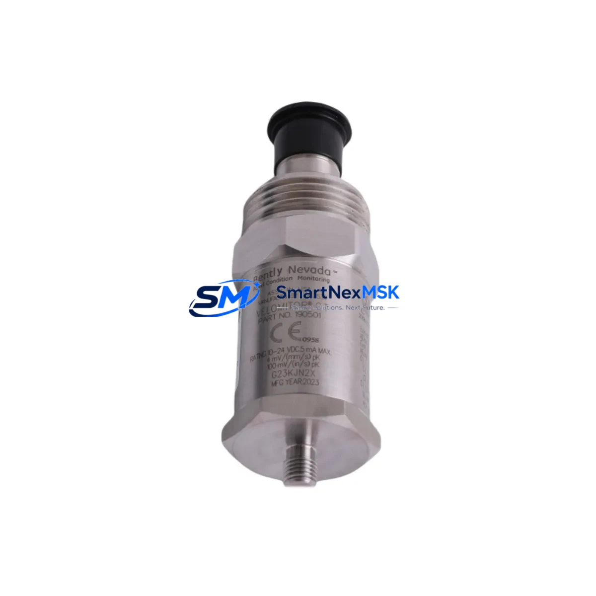
Bently Nevada 190501-20-99-04 Spare for 9000 Automation
The Bently Nevada 190501-20-99-04 is an original seismic velocity transducer engineered for continuous vibration monitoring in rotating machinery protection systems. As a maintenance-ready spare for the Bently Nevada 9000 Series platform, this unit is a critical component in preventing unplanned downtime across compressors, turbines, pumps, and motor-driven equipment in oil & gas, power generation, petrochemical, and heavy industrial facilities.
When a seismic velocity transducer fails or drifts out of calibration, the consequences extend beyond a single sensor replacement. Maintenance engineers must treat this event as a trigger for a broader inspection of the vibration monitoring loop. The 190501-20-99-04 interfaces directly with the 9000 Series monitor rack, and its replacement should be coordinated with a review of the entire signal chain — from the transducer mounting and cable integrity through to the monitor module and DCS input card.
This unit ships fully tested against original Bently Nevada specifications, with documentation confirming output sensitivity, frequency response, and mechanical integrity. Each spare is covered by a 12-month warranty from the date of shipment, providing procurement engineers with the confidence needed for long-term spare parts planning.
Spare Maintenance Table
| Parameter | Specification |
|---|---|
| Part Number | 190501-20-99-04 |
| Brand | Bently Nevada |
| Series | 9000 Series |
| Product Type | Seismic Velocity Transducer |
| Output Type | Velocity (mV/mm/s or mV/in/s) |
| Frequency Range | Typically 10–1000 Hz (seismic band) |
| Mounting | Stud or adhesive mount, per installation standard |
| Connector | Compatible with 9000 Series signal cabling |
| Operating Environment | Industrial — suitable for high-vibration, high-temperature zones |
| Compatibility | Bently Nevada 9000 Series monitor racks and I/O modules |
| Origin | USA |
| Weight | 380 g |
| Pre-shipment Testing | Yes — output sensitivity and mechanical integrity verified |
| Warranty | 12 Months from shipment date |
| Condition | Original spare, new or recertified |
Maintenance Planning for Continuous Operation
Replacing the 190501-20-99-04 in a live plant environment requires more than a direct swap. A structured maintenance approach ensures the replacement restores full system integrity and does not introduce new failure modes. Maintenance engineers should use this replacement event as an opportunity to inspect the following associated components within the same vibration monitoring loop and control cabinet:
Begin with the 9000 Series monitor module that receives the transducer signal. Verify that the input channel is functioning correctly and that no alarm latching or configuration drift has occurred during the fault period. If the monitor module has been in service for more than five years, consider scheduling a bench calibration or stocking a replacement module such as a compatible 9000 Series I/O card.
Inspect the signal cable and field junction box connecting the transducer to the monitor rack. Seismic transducer cables are subject to mechanical fatigue, particularly in high-vibration zones near rotating equipment. Check for insulation damage, connector corrosion, and shield continuity. A faulty cable can produce erratic readings even after a new transducer is installed.
Review the power supply module feeding the 9000 Series rack. Voltage instability or ripple on the 24 VDC rail can affect transducer output accuracy. If the rack shares a power supply with other I/O modules or relay output cards, confirm that the supply is within specification under full load.
Check the relay output module associated with the vibration alarm and trip circuit. Confirm that the relay contacts are clean and that the trip setpoints have not been inadvertently modified. In older 9000 Series installations, relay modules may be approaching end-of-life and should be included in the next planned maintenance window.
If the plant uses a DCS or PLC integration for vibration data — for example, routing 9000 Series analog outputs to a Yokogawa CENTUM VP I/O card or an ABB System 800xA field I/O module — verify that the analog input channel is reading correctly after the transducer replacement. A mismatch in engineering units or scaling can cause false alarms or missed trips.
For facilities using Bently Nevada System 1 software for condition monitoring, confirm that the new transducer’s sensitivity value is correctly entered in the channel configuration. An incorrect sensitivity factor will produce inaccurate velocity readings and may mask developing faults in the monitored machine.
Finally, inspect the terminal blocks and grounding connections within the control cabinet. Loose terminals and poor grounding are among the most common causes of signal noise in seismic monitoring loops. Tighten all connections and verify that the cabinet ground bus is properly bonded.
Site Replacement Workflow
The 190501-20-99-04 is designed as a direct replacement for the original Bently Nevada 9000 Series seismic velocity transducer. The following workflow minimizes downtime and ensures system compatibility is maintained throughout the replacement process:
Step 1 — Isolation and Lockout: Follow site LOTO procedures before accessing the transducer mounting location. Notify the control room to acknowledge the vibration channel and suppress trip functions if required by site procedure.
Step 2 — Physical Removal: Disconnect the signal cable at the field junction box. Remove the transducer from its mounting stud or adhesive pad. Inspect the mounting surface for corrosion or mechanical damage that could affect the new unit’s coupling efficiency.
Step 3 — Installation: Mount the 190501-20-99-04 to the cleaned and prepared surface. Reconnect the signal cable, ensuring correct polarity and shield termination. Torque the mounting stud to the manufacturer’s specification.
Step 4 — Loop Verification: With the channel active, verify that the monitor module is receiving a valid signal within the expected range for the machine’s normal operating condition. Compare the reading against historical baseline data if available in System 1 or the plant historian.
Step 5 — Return to Service: Re-enable the trip function and confirm alarm setpoints. Document the replacement in the plant maintenance management system (CMMS) with the new unit’s serial number and installation date for warranty tracking.
This workflow applies equally to planned maintenance replacements and emergency spare activations. Stocking at least one 190501-20-99-04 in the site spare parts inventory is recommended for facilities where continuous vibration monitoring is critical to machine protection.
Spare Parts Support FAQ
Q1: Is the 190501-20-99-04 a direct replacement for the original Bently Nevada unit in a 9000 Series system?
Yes. The 190501-20-99-04 is an original Bently Nevada seismic velocity transducer specified for the 9000 Series platform. It is a direct replacement for the same part number and maintains full compatibility with the monitor rack, signal cabling, and System 1 software configuration without requiring hardware or software modifications.
Q2: What testing is performed before shipment?
Each unit undergoes pre-shipment verification covering output sensitivity, frequency response, and mechanical integrity. Test results are available upon request. The 12-month warranty covers defects in materials and workmanship from the date of shipment, providing assurance for both planned procurement and emergency replacement scenarios.
Q3: How should I manage spare parts inventory for this transducer?
For facilities with multiple monitored machines, we recommend maintaining a minimum of one to two units of the 190501-20-99-04 in the site spare parts store. Given the lead times associated with original Bently Nevada components, holding a local spare eliminates the risk of extended downtime while awaiting delivery. Spare parts should be stored in a dry, temperature-controlled environment and inspected annually for connector condition and packaging integrity.
Q4: Can compatibility be verified before the unit is shipped?
Yes. Provide your system configuration details — including the 9000 Series monitor model, rack configuration, and any System 1 software version — and our technical team will confirm compatibility before shipment. This service is available at no additional cost and is recommended for first-time replacements or installations where the original documentation is incomplete.
© 2026 SMARTNEXMSK. All rights reserved.
Original Source: https://smartnexmsk.com
Contact: [email protected] | +86 18259474341



