
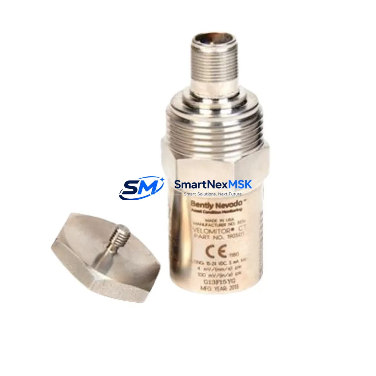
Bently Nevada 190501-21-00-00 Retrofit-Ready Velomitor CT: Seamless Compatibility for Legacy System Upgrades
The Bently Nevada 190501-21-00-00 Velomitor CT is a high-performance velocity transducer engineered for continuous vibration monitoring in rotating machinery applications. Widely deployed across turbines, compressors, pumps, and motors in oil & gas, power generation, and petrochemical facilities, this unit has become a critical component in legacy condition monitoring architectures built around the Bently Nevada 3500 Series Machinery Protection System. As original units reach end-of-life or become increasingly difficult to source through OEM channels, the demand for verified retrofit-ready replacements has grown significantly among maintenance engineers and reliability teams managing aging plant infrastructure.
Our stocked 190501-21-00-00 is a direct drop-in replacement designed to restore full monitoring capability with minimal downtime. It delivers a 4–20 mA output signal compatible with existing field wiring, DCS input cards, and safety instrumented system (SIS) interfaces without requiring signal conditioning modifications. The unit maintains the same mechanical envelope, connector pinout, and mounting thread specification as the original, allowing technicians to complete a swap within a standard maintenance window.
Upgrade Compatibility Table
| Parameter | Details |
|---|---|
| SKU / Part Number | 190501-21-00-00 |
| Brand | Bently Nevada |
| Series Compatibility | Bently Nevada 3500 Series Machinery Protection System |
| Output Signal | 4–20 mA (velocity proportional) |
| Mounting Interface | Standard threaded stud mount — matches OEM specification |
| Connector / Wiring | Drop-in compatible with existing field cable terminations |
| Communication Compatibility | Analog 4–20 mA; compatible with 3500/42M, 3500/45, and 3500/46M monitor cards |
| Replacement Recommendation | Direct replacement for discontinued or end-of-life 190501-21-00-00 units |
| Commissioning Notes | Verify zero-speed offset, full-scale calibration, and alarm setpoints in 3500 rack configuration software after installation |
| Warranty | 12-Month Warranty — covers manufacturing defects and functional performance |
| Origin | Xiamen, China — export-ready with full documentation |
Retrofit Planning for Existing Automation Systems
Replacing the 190501-21-00-00 Velomitor CT within an operational plant environment requires careful coordination across multiple system layers. The transducer interfaces directly with the Bently Nevada 3500 Series rack, typically housed in a dedicated machinery protection cabinet alongside monitor modules such as the 3500/42M Proximitor/Seismic Monitor or the 3500/45 Position Monitor. Before initiating a swap, the maintenance team should confirm that the rack’s I/O channel assignment for the affected machine train remains unchanged and that the monitor card firmware version supports the replacement unit’s output characteristics.
Field wiring from the transducer to the 3500 rack terminal block should be inspected for insulation integrity, shield continuity, and correct polarity. The 190501-21-00-00 uses a two-wire 4–20 mA loop; technicians should verify loop resistance and supply voltage at the barrier or isolator — commonly a Bently Nevada 3500/20 Power Supply module — to ensure the replacement unit operates within its specified current range. If the existing installation includes a Bently Nevada 3500/22M Transient Data Interface, confirm that the channel configuration in System 1 software reflects the correct transducer sensitivity and engineering unit scaling before re-enabling the channel.
For plants running a hybrid architecture where the 3500 rack feeds analog signals into a DCS such as a Honeywell Experion PKS or an Emerson DeltaV, the 4–20 mA signal path through the marshalling cabinet should be traced and verified end-to-end. Any intermediate signal conditioners, galvanic isolators, or intrinsic safety barriers in the loop must be confirmed compatible with the replacement unit’s output impedance. HMI faceplates displaying velocity trend data should be reviewed to ensure engineering unit conversion factors and alarm thresholds remain valid after the swap.
In retrofit scenarios involving a broader migration from the legacy 3500 platform toward a newer Bently Nevada System 1 Evolution architecture, the 190501-21-00-00 Velomitor CT remains fully compatible as a field sensor, allowing the transducer layer to be retained while the monitoring and data acquisition infrastructure is upgraded. This approach significantly reduces the scope and cost of the migration by decoupling the sensor replacement cycle from the rack and software upgrade schedule. Related components commonly addressed in the same migration window include the Bently Nevada 3500/15 Power Supply, 3500/32 4-Channel Relay Module, 3500/92 Communication Gateway Module, and the Bently Nevada TK-3 Proximitor extension cable assemblies used to route signals from machine-mounted proximity probes to the rack.
Where the plant’s condition monitoring strategy includes portable data collection using a CSI 2140 Machinery Health Analyzer or similar route-based device, the replacement Velomitor CT should be verified against the analyzer’s sensor database to ensure correct sensitivity coefficients are applied during route measurements. This prevents false alarm conditions and ensures trend data continuity across the maintenance history database.
Downtime Control During System Migration
Minimizing unplanned downtime during a Velomitor CT replacement is achievable through disciplined pre-work and a structured hot-swap protocol. Begin by placing the affected monitor channel in bypass mode within the 3500 rack configuration software — this suppresses alarm and trip outputs for the channel while the machine remains online, preserving production continuity. Document the current alarm setpoints, full-scale range, and channel tag before entering bypass to ensure exact restoration after commissioning the replacement unit.
Physical replacement should be performed with the machine at rest wherever possible. Once the 190501-21-00-00 is installed and wiring is reconnected, perform a loop check by injecting a known 4 mA and 20 mA signal at the field terminal to verify correct reading at the 3500 monitor card and at the DCS historian. Confirm that the System 1 or equivalent condition monitoring software is receiving a valid, in-range signal before removing the channel bypass. Re-enable alarms and verify that the first-out trip logic for the machine train is restored to its pre-maintenance state.
For facilities operating under IEC 61511 functional safety requirements, the replacement procedure should be documented as a proof test activity, with the as-found and as-left channel readings recorded in the safety management system. The 12-month warranty on the replacement unit supports the proof test interval requirements of most SIL 1 and SIL 2 rated overspeed and vibration protection loops, providing a documented basis for the maintenance record.
Pre-shipment functional testing is performed on every unit before dispatch. Each 190501-21-00-00 is verified for output linearity, zero-speed offset, and connector integrity, with a test report available upon request. Units are packaged with ESD protection and shipped with full export documentation to support customs clearance for international destinations.
Retrofit Support FAQ
Q1: Is the 190501-21-00-00 a direct drop-in replacement for the original Bently Nevada unit?
Yes. The replacement unit matches the original mechanical dimensions, thread specification, connector pinout, and 4–20 mA output signal. No field wiring modifications or signal conditioning changes are required for a standard swap in a 3500 Series rack installation.
Q2: What commissioning steps are required after installation?
After physical installation and wiring reconnection, perform a loop check to verify signal integrity from the transducer to the monitor card. Confirm channel configuration in the 3500 rack software — including sensitivity, full-scale range, and alarm setpoints — and remove the channel bypass before returning the machine to service. For System 1 connected installations, verify that the historian is receiving a valid trend signal.
Q3: Is the unit compatible with intrinsic safety barriers and galvanic isolators in the signal loop?
Yes, provided the barrier or isolator is rated for a 4–20 mA two-wire loop and the loop supply voltage and resistance budget are within the transducer’s specified operating range. Consult the barrier manufacturer’s entity parameters and verify compatibility with the transducer’s input voltage and current specifications before installation in a hazardous area loop.
Q4: What does the 12-month warranty cover, and what documentation is provided?
The 12-month warranty covers manufacturing defects and functional performance failure under normal operating conditions. Each unit ships with a pre-shipment test report confirming output linearity and connector integrity. A certificate of conformance and commercial invoice are included for customs and quality management system documentation purposes. Warranty claims are processed through our technical support team at [email protected].
© 2026 SMARTNEXMSK. All rights reserved.
Original Source: https://smartnexmsk.com
Contact: [email protected] | +86 18259474341



