
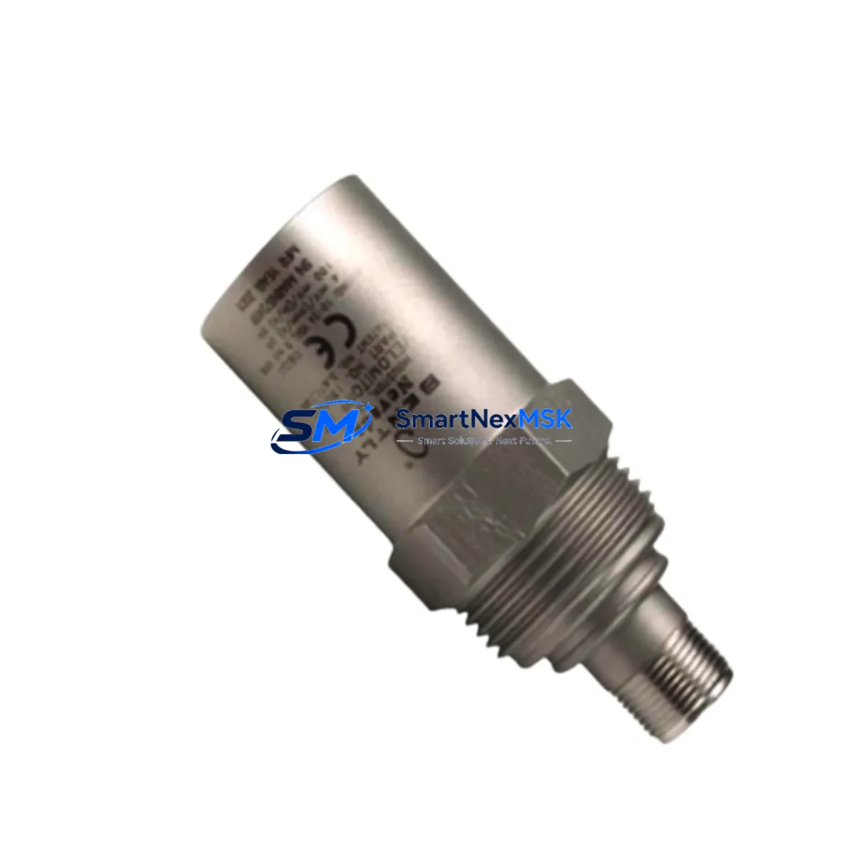
Bently Nevada 190501-21-00-01 Retrofit-Ready Velocity Sensor: Seamless Compatibility for Legacy System Upgrades
The Bently Nevada 190501-21-00-01 Velomitor CT is a high-performance seismic velocity transducer engineered for direct retrofit into existing Bently Nevada 3500 Series machinery protection systems and legacy 7200 Series monitoring platforms. As original 190501-series units reach end-of-life or become increasingly difficult to source, this module provides a verified drop-in replacement path that preserves existing wiring infrastructure, terminal assignments, and signal conditioning compatibility — minimizing engineering rework and unplanned downtime during system modernization projects.
Designed for industrial environments where continuous machinery monitoring is non-negotiable, the 190501-21-00-01 delivers broadband velocity measurement across rotating equipment including turbines, compressors, pumps, and motors. Its rugged stainless-steel housing and hermetically sealed construction make it suitable for harsh plant environments with exposure to moisture, vibration, and chemical contaminants. The unit outputs a velocity signal directly compatible with Bently Nevada 3500/42M Velocity and Acceleration Monitor input channels, eliminating the need for signal converters or intermediate conditioning modules.
For facilities operating legacy Bently Nevada 7200 Series proximitor systems or transitioning to the 3500 platform, the 190501-21-00-01 supports a structured migration path. Engineers can retain existing Bently Nevada 3500/20 Rack Power Supply infrastructure and continue using established Bently Nevada 3500/22M Transient Data Interface configurations without modification. The transducer’s two-wire connection scheme is fully compatible with standard Bently Nevada TK-3 extension cables and existing field junction boxes, reducing installation labor and eliminating the need for new cable pulls in most retrofit scenarios.
Upgrade Compatibility Table
| Parameter | 190501-21-00-01 (This Unit) | Retrofit Notes |
|---|---|---|
| Mounting Interface | 1/4-28 UNF threaded stud | Direct replacement for standard Velomitor CT mounting pads; no adapter required |
| Electrical Connection | 2-wire, integral cable | Compatible with existing TK-3 extension cable and field terminal blocks |
| Output Signal | Velocity (mV/mm/s) | Direct input to 3500/42M monitor; no signal conditioning required |
| Communication Compatibility | Analog velocity signal | Compatible with 3500 Series Rack Communication Gateway (3500/92) for Modbus/TCP and OPC-DA integration |
| Power Requirement | 18–30 VDC (loop powered) | Verify 3500/20 rack power supply capacity before adding additional transducer channels |
| Installation Requirement | Torque to 14 N·m; apply thread sealant | Confirm mounting surface flatness; clean threads before installation |
| Replacement Recommendation | Direct replacement for 190501-21-00-01 and compatible 190501-series variants | Verify suffix codes for cable length and connector type before ordering |
| Commissioning Focus | Zero-speed signal check; full-speed vibration baseline | Compare baseline to historical trend data in System 1 Evolution software |
| Warranty | 12 Months | Covers manufacturing defects; includes pre-shipment functional test certificate |
Retrofit Planning for Existing Automation Systems
Successful integration of the 190501-21-00-01 into an operating plant begins with a structured pre-retrofit assessment. Before removing the existing transducer, technicians should document the current vibration baseline using Bently Nevada System 1 Evolution condition monitoring software, capturing trend data, alarm setpoints, and danger thresholds configured in the 3500/42M monitor. This baseline becomes the reference for post-installation commissioning and acceptance testing.
Power budget verification is a critical first step. The Bently Nevada 3500/20 Rack Power Supply supports a defined number of active transducer channels; adding or replacing velocity transducers requires confirming available current headroom. In systems where the rack also powers Bently Nevada 3500/40M Proximitor/Seismic Monitor modules and 3500/50 Tachometer modules, the aggregate current draw must be recalculated before proceeding.
Terminal wiring should be verified against the original installation drawing. The 190501-21-00-01 uses a standard two-wire configuration terminating at the 3500/42M I/O module terminal block. In legacy installations using Bently Nevada 3300 Series monitors, a wiring adapter or signal conditioning relay may be required to bridge the terminal assignment differences. Technicians should also inspect the condition of existing Bently Nevada TK-3 extension cables for insulation degradation, particularly in high-temperature zones near turbine casings.
For facilities integrating the replacement transducer into a DCS environment — such as systems running on Emerson DeltaV or Honeywell Experion PKS — the 3500 rack’s communication gateway must be confirmed operational. The Bently Nevada 3500/92 Rack Communication Gateway supports Modbus/TCP and OPC-DA protocols, enabling real-time vibration data to flow into the DCS historian without additional hardware. Where HMI screens in the control room display vibration trends from the replaced transducer channel, the HMI tag mapping should be verified post-replacement to confirm the new signal is correctly associated with the display faceplate.
Module address configuration within the 3500 rack is managed through Rack Configuration software. After physical installation, the technician must confirm that the channel assignment for the new 190501-21-00-01 matches the slot address previously occupied by the legacy unit. Incorrect slot addressing will result in the monitor reporting a not-OK condition and may trigger a system alarm in the DCS. A Bently Nevada 3500/94 Ethernet I/O Module, if present in the rack, should also be checked to confirm that its channel mapping reflects the updated transducer configuration.
All units are pre-shipment tested against Bently Nevada factory acceptance criteria and supplied with a functional test certificate. Stock is maintained for immediate dispatch, supporting urgent replacement requirements in operating plants where extended downtime is not acceptable.
Downtime Control During System Migration
Minimizing production interruption during a velocity transducer replacement requires careful sequencing of isolation, replacement, and recommissioning steps. Where process conditions permit, the preferred approach is a hot-swap procedure: the 3500/42M monitor channel is placed in bypass mode using the rack’s configuration software, allowing the machine to continue operating while the transducer is replaced. Bypass mode suppresses the alarm and danger outputs for the affected channel without affecting adjacent channels or the overall rack health status.
Once the 190501-21-00-01 is physically installed and wiring verified, the channel is brought out of bypass and the signal is observed in real time through System 1 Evolution or the rack’s front-panel display. The technician confirms that the output signal is within the expected range for the machine’s current operating speed and load condition. If the signal deviates from the pre-replacement baseline by more than the acceptance tolerance defined in the site’s maintenance procedure, the installation should be reviewed before the bypass is fully removed.
For machines that cannot be operated during transducer replacement — such as critical compressors or steam turbines with mandatory isolation requirements — the replacement window should be coordinated with the planned maintenance schedule. In these cases, the full recommissioning sequence includes a slow-roll vibration check at minimum governor speed, a coast-down data capture using the 3500/42M’s transient recording capability, and a comparison of the new baseline against the historical trend archive. This approach ensures that the replacement transducer is performing correctly before the machine is returned to full load, protecting both the equipment and the integrity of the condition monitoring program.
Original program logic in the DCS or safety instrumented system (SIS) does not require modification when replacing a like-for-like 190501-series transducer, provided the signal range and alarm setpoints remain unchanged. Where the replacement is part of a broader system upgrade — for example, migrating from a 3300 Series rack to a 3500 Series rack — the SIS logic should be reviewed by a qualified functional safety engineer before the system is returned to service.
Retrofit Support FAQ
Q: Is the 190501-21-00-01 a direct replacement for other 190501-series suffix variants?
A: The 190501 series uses suffix codes to designate cable length and connector type. The -21-00-01 suffix specifies a particular cable configuration. Before ordering, confirm that the suffix of the replacement unit matches the original installation’s cable length and termination requirements. In most cases, the transducer body and sensing element are identical across suffix variants; only the integral cable assembly differs.
Q: What commissioning steps are required after installation?
A: After physical installation and wiring verification, connect to the 3500 rack via Rack Configuration software and confirm the channel is active and reporting a valid signal. Perform a zero-speed check to verify the output is within the specified quiescent range, then observe the signal at operating speed and compare to the pre-replacement baseline. Document the as-found and as-left readings in the site’s maintenance management system.
Q: Can this transducer be used with non-Bently Nevada monitoring systems?
A: The 190501-21-00-01 outputs a standard velocity signal that is compatible with most industrial vibration monitoring systems accepting a millivolt-per-velocity input. However, full compatibility should be verified against the target monitor’s input specification, particularly with respect to supply voltage range, cable capacitance limits, and signal conditioning requirements. Use with non-Bently Nevada systems may affect warranty coverage.
Q: What does the 12-month warranty cover?
A: The 12-month warranty covers manufacturing defects in materials and workmanship from the date of shipment. Each unit is functionally tested prior to dispatch and supplied with a test certificate. Warranty claims require return of the defective unit for inspection. The warranty does not cover damage resulting from incorrect installation, overvoltage, or use outside the specified environmental limits.
© 2026 SMARTNEXMSK. All rights reserved.
Original Source: https://smartnexmsk.com
Contact: [email protected] | +86 18259474341



