
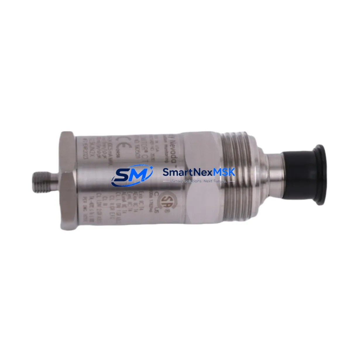
Bently Nevada 190501-21-99-04 Retrofit-Ready Seismic Velocity Transducer for 190501 Series Control Systems
The Bently Nevada 190501-21-99-04 is a seismic velocity transducer engineered for direct retrofit into existing 190501 Series vibration monitoring installations. As legacy machinery protection systems age and original components reach end-of-life, plant engineers face increasing pressure to source compatible replacements that preserve existing wiring infrastructure, rack architecture, and signal conditioning logic without triggering a full system overhaul. This unit addresses that challenge directly — offering a verified drop-in replacement path for facilities running Bently Nevada 3500 Series machinery protection racks, 7200 Series proximity systems, and associated Keyphasor modules.
Designed for continuous operation in heavy industrial environments including turbomachinery, compressor trains, pumps, and rotating equipment platforms, the 190501-21-99-04 delivers reliable velocity output compatible with the signal conditioning inputs of the 3500/42M Proximitor/Seismic Monitor module. Engineers migrating from discontinued 190501 variants can retain existing terminal block wiring, cable runs, and rack slot assignments, significantly reducing retrofit labor and downtime exposure.
Upgrade Compatibility Table
| Parameter | Details |
|---|---|
| SKU / Part Number | 190501-21-99-04 |
| Brand / OEM | Bently Nevada |
| Series Compatibility | 190501 Series; 3500 Series Rack |
| Transducer Type | Seismic Velocity (Electrodynamic) |
| Mounting Interface | Standard threaded stud mount; compatible with existing 190501 Series brackets |
| Signal Output | Velocity (mV/mm/s or mV/in/s per configuration) |
| Wiring Compatibility | Retains existing 2-wire field cable; no re-termination required in most installations |
| Rack / Backplane Interface | Compatible with 3500/42M Proximitor/Seismic Monitor input channels |
| Communication Protocol | Analog signal; compatible with 3500 Series System 1 Evolution software integration |
| Replacement Recommendation | Direct replacement for discontinued 190501-21-xx-xx variants |
| Commissioning Notes | Verify sensitivity scaling in monitor module; confirm OK/Not OK setpoints post-installation |
| Warranty | 12-Month Warranty from date of shipment |
Retrofit Planning for Existing Automation Systems
Successful integration of the 190501-21-99-04 into a running plant begins well before the unit arrives on site. Retrofit planning should start with a full audit of the existing 3500 Series rack configuration, including the slot assignments of the 3500/20 Rack Interface Module, the 3500/15 Power Supply Module, and any 3500/22M Transient Data Interface cards currently installed. Understanding the rack’s power budget is critical — the 3500/15 supplies a fixed DC bus to all installed monitor modules, and adding or swapping transducer types can affect channel loading if the rack is near capacity.
Terminal block wiring should be documented before removal. The 190501-21-99-04 uses the same pinout convention as earlier 190501 variants, but field technicians should verify shield grounding continuity and confirm that the existing Bently Nevada 3500/42M input channel is configured for seismic (velocity) input rather than proximity (displacement) mode. This configuration is set via the rack’s System 1 software or the dedicated 3500 Rack Configuration Software, and an incorrect channel type setting will result in erroneous OK/Not OK relay outputs.
For facilities also managing Keyphasor signals — common in turbine and compressor applications — confirm that the 3500/25 Keyphasor Module channel assignments remain undisturbed during the transducer swap. Keyphasor reference signals are shared across multiple monitor channels, and any disruption to the Keyphasor loop during maintenance windows can trigger spurious alarms across the entire rack. Similarly, if the plant uses a 3500/92 Communication Gateway Module for Modbus or Ethernet/IP integration to a DCS or SCADA platform, verify that the gateway’s tag mapping for the affected channel is preserved after the replacement unit is commissioned.
Where the existing installation includes a Bently Nevada TK-3 Proximitor Extension Cable or field junction box, inspect connector integrity and cable insulation before re-energizing the loop. Degraded cable insulation is a common source of noise and false alarms in legacy seismic monitoring circuits and should be addressed during the same maintenance window to avoid repeat outages.
Downtime Control During System Migration
Minimizing production downtime during a transducer replacement requires a structured pre-outage preparation protocol. Before the maintenance window opens, technicians should download and archive the current 3500 rack configuration using the Rack Configuration Software, capturing all channel sensitivity values, full-scale ranges, alarm setpoints, and relay logic assignments. This configuration file serves as both a restoration baseline and a commissioning checklist for the replacement unit.
During the swap, the 3500/42M monitor channel associated with the 190501-21-99-04 should be placed in bypass mode to suppress spurious alarms and prevent inadvertent relay trips to the machinery protection shutdown circuit. Most 3500 Series racks support per-channel bypass via the front-panel keypad or System 1 software without requiring a full rack power cycle, which preserves monitoring continuity on adjacent channels and protects other critical measurement points — such as radial vibration channels using 7200 Series proximity probes — from unnecessary interruption.
After physical installation, perform a bench-level sensitivity verification using a calibrated vibration reference source before returning the channel to active monitoring. Confirm that the OK relay output is healthy, that the vibration reading tracks the reference input within the specified tolerance, and that the System 1 trend display reflects live data from the new transducer. Only after these checks are complete should the bypass be removed and the channel returned to full protective service. This sequence typically allows a complete transducer replacement to be executed within a two-to-four hour planned outage window, even in complex multi-rack installations.
All units are pre-tested prior to shipment and supplied with a test report. In-stock inventory supports same-week dispatch for urgent replacement requirements. 12-month warranty coverage applies from the date of shipment.
Retrofit Support FAQ
Q: Is the 190501-21-99-04 a direct replacement for other 190501 suffix variants?
A: The 190501-21-99-04 is directly interchangeable with most 190501-21-xx-xx suffix variants within the same mounting and cable configuration. Suffix digits encode options such as cable length, connector type, and temperature rating. Confirm your existing suffix against the 190501 Series datasheet to verify dimensional and electrical compatibility before installation. Where suffix differences exist, our technical team can advise on any required adapter hardware.
Q: Do I need to reconfigure the 3500/42M monitor module after installing the replacement transducer?
A: In most cases, no reconfiguration is required if the replacement unit matches the sensitivity specification of the original. However, it is best practice to verify the channel sensitivity setting in the Rack Configuration Software and confirm that full-scale range and alarm setpoints remain appropriate for the new unit’s output characteristics. Any deviation in sensitivity (mV/mm/s) between the old and new transducer will require a proportional adjustment to the monitor’s scale factor.
Q: What wiring changes are needed at the terminal block?
A: The 190501-21-99-04 uses the same 2-wire connection convention as earlier 190501 Series units. In the majority of installations, existing field cable terminations can be reused without modification. Technicians should inspect terminal screw torque, verify shield drain wire continuity, and confirm that no ground loops exist between the transducer body and the rack chassis before re-energizing the loop.
Q: What does the 12-month warranty cover, and is pre-shipment testing included?
A: Every 190501-21-99-04 unit undergoes functional testing prior to dispatch, including sensitivity verification and output signal integrity checks. The 12-month warranty covers manufacturing defects and functional failures under normal operating conditions from the date of shipment. Warranty claims are supported with direct technical assistance and expedited replacement dispatch to minimize plant downtime.
© 2026 SMARTNEXMSK. All rights reserved.
Original Source: https://smartnexmsk.com
Contact: [email protected] | +86 18259474341



