
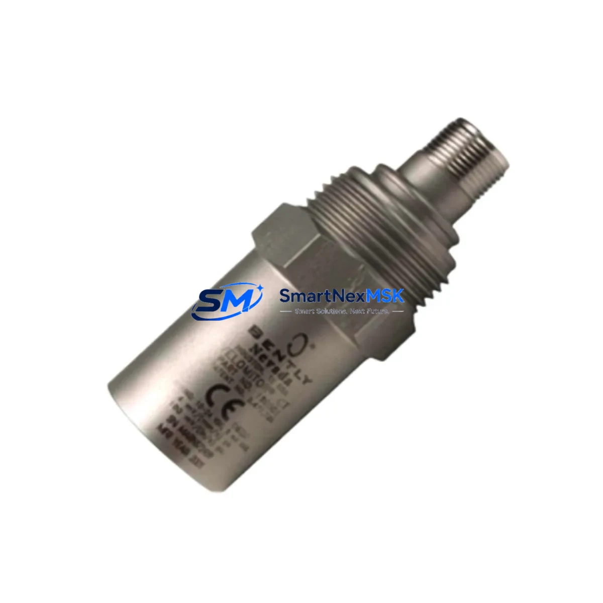
Bently Nevada 190501-22-00-01 Spare Velomitor CT Automation: Spare Replacement & Industrial Downtime Risk Control
The Bently Nevada 190501-22-00-01 Velomitor CT is a high-sensitivity velocity transducer engineered for continuous vibration monitoring in rotating machinery protection systems. As a maintenance-ready original spare, this unit is stocked and tested to support rapid field replacement, minimizing unplanned downtime in critical industrial environments including power generation, oil & gas, petrochemical, and heavy manufacturing facilities.
Maintenance engineers and procurement teams operating Bently Nevada 3500 Series machinery protection systems rely on the 190501-22-00-01 as a front-line sensing component. Its seismic velocity output integrates directly with 3500/42M velocity and acceleration monitor modules, enabling real-time shaft and casing vibration trending. When this transducer reaches end-of-life or exhibits signal drift, immediate replacement with a verified original spare is essential to maintain system integrity and avoid false trips or missed alarms.
Every unit shipped from our inventory undergoes pre-dispatch functional verification, including output sensitivity check, cable continuity test, and connector integrity inspection. Our 12-month warranty covers manufacturing defects and ensures long-term supply reliability for your spare parts program.
Spare Maintenance Table
| Parameter | Specification |
|---|---|
| Part Number | 190501-22-00-01 |
| Brand | Bently Nevada |
| Series | Velomitor CT |
| Product Type | Velocity Transducer (Seismic) |
| Output Sensitivity | 100 mV/in/s (nominal) |
| Frequency Range | 2 Hz – 1,000 Hz |
| Operating Temperature | -40°C to +121°C |
| Connector Type | 2-pin MIL-C-5015 style |
| Cable Length | Integral cable, 5 m (standard) |
| Compatibility | Bently Nevada 3500/42M, 3500/40M, 3300 Series monitors |
| Mounting | Stud mount, 1/4-28 UNF thread |
| Origin | USA |
| Application Environment | Rotating machinery, turbines, compressors, pumps, motors |
| Maintenance Recommendation | Inspect every 12 months or at planned shutdown; replace on signal drift >10% |
| Warranty | 12 Months |
| Shipping | Tested & inspected before dispatch; global shipping available |
Maintenance Planning for Continuous Operation
When scheduling replacement of the 190501-22-00-01 Velomitor CT, a thorough inspection of the surrounding measurement chain and control cabinet is strongly recommended. Maintenance engineers should treat this as an opportunity to audit the full vibration monitoring loop and associated protection circuitry.
Begin by verifying the condition of the Bently Nevada 3500/42M Velocity/Acceleration Monitor module seated in the 3500 rack. Signal conditioning faults at the monitor level can mimic transducer failure and lead to unnecessary replacements. Simultaneously, inspect the 3500/20 Rack Interface Module (RIM) for communication integrity with the host DCS or safety system.
Check the 3500/15 Power Supply Module output voltage stability — an unstable rack power supply is a common root cause of intermittent transducer signal anomalies. If the rack houses multiple channels, also inspect the 3500/22M Transient Data Interface for any buffered output faults that could affect trending data quality.
For the field wiring side, inspect the Bently Nevada 330130 series extension cables and junction boxes for moisture ingress, connector corrosion, or shield continuity breaks — particularly in outdoor or high-humidity installations. Damaged extension cables are a frequent cause of elevated noise floors in velocity measurements.
If the machinery protection system interfaces with a Bently Nevada 3500/92 Communication Gateway for Modbus or Ethernet/IP output to the plant DCS, verify that the gateway firmware and configuration remain intact after any rack power cycle. Additionally, review the status of any signal isolators or barriers installed between the 3500 rack outputs and the DCS analog input cards — degraded isolation can introduce ground loops that corrupt velocity readings.
For facilities running legacy Bently Nevada 3300 Series monitors alongside newer 3500 racks, confirm that the 190501-22-00-01 sensitivity and connector pinout are compatible with the installed monitor version before installation. Where HMI trending screens are used for vibration visualization, validate that the operator workstation running System 1 or equivalent condition monitoring software reflects the new transducer calibration data after replacement.
Finally, ensure that terminal blocks and DIN rail assemblies within the control cabinet are torqued to specification and free of oxidation, as loose terminations at the signal input terminals of the monitor module can produce spurious high-vibration alarms immediately after a transducer swap.
Site Replacement Workflow
Step 1 — Pre-replacement verification: Confirm the installed transducer part number against the as-built drawing. Verify that the 190501-22-00-01 is the correct replacement for the existing unit, including connector type, cable length, and sensitivity specification. Cross-reference with the 3500/42M channel configuration to ensure the monitor is set for velocity input.
Step 2 — Safe isolation: Follow site lock-out/tag-out (LOTO) procedures. Inhibit the affected monitor channel in the 3500 rack to prevent spurious trips during the swap. Document the pre-replacement vibration baseline from the System 1 historian or DCS trend display.
Step 3 — Physical replacement: Remove the existing transducer by disconnecting the extension cable at the junction box. Clean the mounting surface and inspect the stud thread condition. Install the 190501-22-00-01 to the specified torque. Reconnect the extension cable, ensuring the connector is fully seated and the locking ring is secure.
Step 4 — Signal verification: Re-enable the monitor channel and observe the live vibration reading. Compare against the pre-replacement baseline and adjacent channel readings. A healthy Velomitor CT installation should show a stable, low-noise signal consistent with the machine’s normal vibration signature.
Step 5 — Documentation: Record the replacement in the maintenance management system (CMMS), including the new unit serial number, installation date, and post-replacement vibration reading. Update the spare parts inventory to trigger reorder of a replacement unit, maintaining minimum stock levels for critical machinery.
This workflow supports rapid downtime recovery — typically achievable within 2–4 hours for a single-channel replacement — while maintaining full system compatibility and measurement traceability.
Spare Parts Support FAQ
Q1: Is the 190501-22-00-01 a direct drop-in replacement for older Velomitor CT variants?
A: The 190501-22-00-01 is the current production part number for the Velomitor CT seismic velocity transducer. It is compatible with Bently Nevada 3500/42M and 3300 Series monitors. For installations using earlier Velomitor variants with different connector configurations, verify the pinout and sensitivity against the monitor channel setup before installation. Our technical team can assist with compatibility confirmation prior to shipment.
Q2: What pre-shipment testing is performed on each unit?
A: Every 190501-22-00-01 unit undergoes functional verification before dispatch, including output sensitivity measurement, cable continuity check, and connector integrity inspection. Units are shipped with a test record. The 12-month warranty covers manufacturing defects identified during installation or operation within the warranty period.
Q3: How should we manage spare inventory for critical rotating machinery?
A: For machinery classified as critical (single-train compressors, main turbines, boiler feed pumps), we recommend maintaining a minimum of one spare 190501-22-00-01 per monitored machine on-site, with a second unit held at the central warehouse. Planned replacement intervals of 5–7 years or on condition (signal drift >10% from baseline) are typical industry practice. We support long-term supply agreements to ensure consistent availability.
Q4: Can you supply the 190501-22-00-01 for emergency same-day or next-day dispatch?
A: Yes. For emergency breakdown situations, we prioritize order processing and can arrange same-day dispatch for in-stock units. Contact our sales team directly with your purchase order and shipping requirements. We support air freight to most global destinations to minimize machinery downtime.
© 2026 SMARTNEXMSK. All rights reserved.
Original Source: https://smartnexmsk.com
Contact: [email protected] | +86 18259474341



