
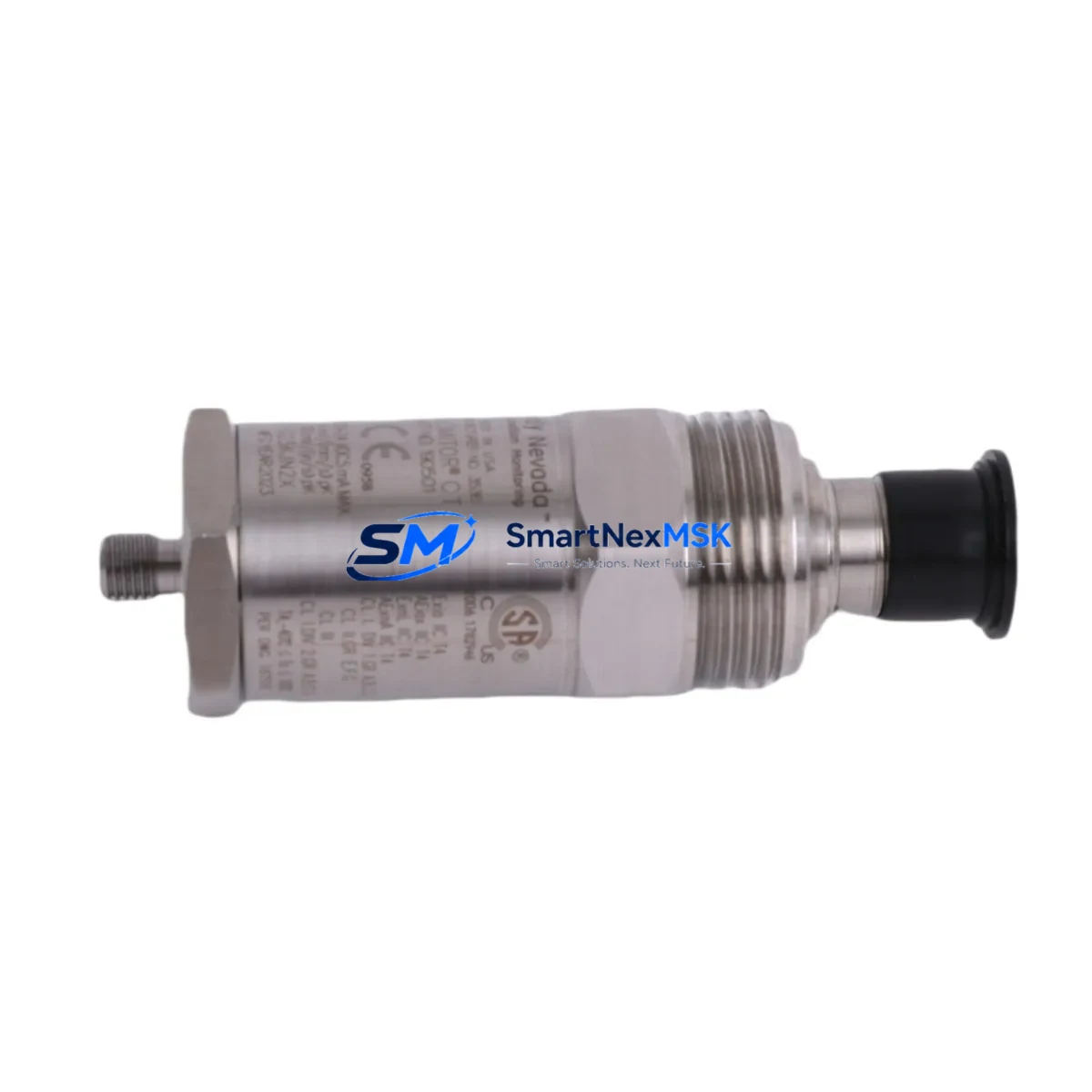
Bently Nevada 190501-23-00-00 Velomitor CT Spare: Precision Velocity Sensing for Industrial Uptime
The Bently Nevada 190501-23-00-00 is a Velomitor CT series piezoelectric velocity transducer engineered for continuous vibration monitoring on rotating machinery in critical industrial environments. As a maintenance-ready original spare, this unit delivers reliable velocity signal output across compressors, turbines, pumps, fans, and gearboxes — enabling maintenance teams to execute rapid fault isolation and minimize unplanned downtime. With a 4–1000 Hz frequency response and a nominal sensitivity of 100 mV/in/s (3.937 mV/mm/s), the 190501-23-00-00 integrates directly into Bently Nevada 3500 Series monitoring racks and compatible vibration monitoring systems without signal conditioning modifications.
For maintenance engineers managing aging control systems or executing planned turnaround inspections, having a verified spare of the 190501-23-00-00 on the shelf is a cornerstone of any proactive vibration monitoring strategy. The Velomitor CT’s self-generating design eliminates the need for external power supply to the transducer element itself, reducing wiring complexity during emergency replacements. Its rugged stainless steel housing and hermetically sealed construction make it suitable for harsh plant environments including petrochemical, power generation, and heavy manufacturing facilities.
Spare Maintenance Table
| Parameter | Specification |
|---|---|
| Part Number / SKU | 190501-23-00-00 |
| Brand | Bently Nevada |
| Series | Velomitor CT |
| Product Type | Piezoelectric Velocity Transducer |
| Sensitivity | 100 mV/in/s (3.937 mV/mm/s) nominal |
| Frequency Response | 4 Hz – 1,000 Hz (±3 dB) |
| Output Signal | Analog voltage (self-generating) |
| Operating Temperature | -40°C to +121°C (-40°F to +250°F) |
| Housing Material | 316 Stainless Steel |
| Mounting | 1/4-28 UNF threaded stud |
| Connector | 2-pin MIL-C-5015 style |
| Compatible Systems | Bently Nevada 3500 Series, 2300 Series, ADRE Sxp |
| Application | Compressors, turbines, pumps, fans, gearboxes |
| Origin | USA (OEM) |
| Condition | New / Surplus New |
| Pre-shipment Testing | Functional output verification performed |
| Warranty | 12 Months from date of shipment |
Maintenance Planning for Continuous Operation
When replacing the 190501-23-00-00 Velomitor CT transducer during a scheduled outage or emergency callout, a thorough inspection of the surrounding measurement loop is essential to ensure the replacement delivers accurate data from day one. Begin by verifying the integrity of the Bently Nevada 330130 or 330180 series extension cables — damaged or corroded cable jackets are a leading cause of signal noise that can mask genuine vibration anomalies. Inspect the 3500/42M Proximitor / Seismic Monitor module in the 3500 rack for any alarm LED indications or configuration drift that may have occurred during the fault event.
Check the 3500/15 Power Supply module output voltage under load; a degraded power supply can introduce ripple into velocity channels and produce false high-vibration alarms. If the installation uses a 3500/20 Rack Interface Module (RIM) for Modbus or Ethernet communication to the DCS, confirm that the module firmware is current and that the channel mapping for the replaced transducer is correctly assigned. For installations where the 190501-23-00-00 feeds into a Bently Nevada ADRE Sxp data acquisition system, re-run the channel calibration wizard after installation to re-establish the baseline vibration signature.
In control cabinets housing the 3500 rack, also inspect terminal blocks and field wiring junction boxes for moisture ingress, loose terminations, or oxidized contacts — particularly in outdoor or coastal environments. Where signal isolation is required between the transducer loop and the DCS analog input card, verify that any installed signal isolators or galvanic isolators are within their rated bandwidth for the 4–1000 Hz velocity signal. Fuse holders protecting the transducer circuit should be checked for continuity; a high-resistance fuse contact can introduce measurement error without triggering a blown-fuse alarm. Finally, if the machine also carries Bently Nevada 3300 XL 8mm proximity probes for shaft displacement monitoring alongside the Velomitor CT for casing velocity, confirm that both measurement channels are operational before returning the machine to service — a complete vibration picture requires both displacement and velocity data.
Site Replacement Workflow
Step 1 — Isolation & Lockout: Follow site LOTO procedures. De-energize the 3500 rack channel or place the monitor in bypass mode to prevent spurious alarms during transducer swap.
Step 2 — Remove Legacy Unit: Disconnect the field cable connector and unthread the 190501-23-00-00 (or its predecessor model) from the mounting pad. Inspect the mounting surface for corrosion or thread damage; re-tap if necessary before installing the replacement.
Step 3 — Install Replacement: Thread the new 190501-23-00-00 to the manufacturer-specified torque (typically 20–25 in-lb for 1/4-28 stud). Reconnect the field cable, ensuring the connector is fully seated and the locking ring is engaged.
Step 4 — Signal Verification: Restore power to the monitor channel. Using a portable vibration analyzer or the 3500 rack’s built-in OK relay status, confirm the transducer output is within the expected quiescent voltage range (typically 0 V DC for a self-generating velocity sensor at rest). Apply a known vibration reference if available to verify sensitivity.
Step 5 — Alarm Reinstatement: Remove bypass mode, confirm alert and danger setpoints are active, and document the replacement in the site maintenance management system (CMMS). Update the spare parts inventory to trigger reorder of a replacement 190501-23-00-00 to maintain minimum stock levels.
This workflow is compatible with direct replacement of earlier Velomitor CT variants and supports seamless integration with existing 3500 Series rack configurations without hardware modifications, protecting your capital investment in the monitoring infrastructure.
Spare Parts Support FAQ
Q1: Is the 190501-23-00-00 a direct drop-in replacement for earlier Velomitor CT models?
Yes. The 190501-23-00-00 maintains dimensional, electrical, and connector compatibility with the Velomitor CT product family. It can replace earlier suffix variants in most installations without changes to cabling, mounting hardware, or monitor configuration. Always verify the sensitivity specification matches the channel configuration in your 3500 monitor before installation.
Q2: How is the unit tested before shipment?
Each 190501-23-00-00 unit undergoes functional output verification prior to dispatch, confirming the transducer produces a measurable signal response within the rated sensitivity tolerance. Units are individually packaged with anti-static and shock-protective materials to preserve calibration integrity during transit.
Q3: What is the recommended spare parts stocking strategy for the Velomitor CT?
For critical rotating machinery applications, a minimum of one spare 190501-23-00-00 per monitored machine train is recommended, with additional units held for facilities operating multiple identical machines. Given the transducer’s role in continuous protection monitoring, a zero-spare posture creates unacceptable downtime risk. Long-term supply availability is supported through our stocking program.
Q4: What does the 12-month warranty cover?
The 12-month warranty covers manufacturing defects and functional failures under normal operating conditions from the date of shipment. It does not cover damage resulting from improper installation, over-torquing, exposure to conditions beyond the rated operating envelope, or physical impact. Warranty claims are supported with replacement unit dispatch upon confirmation of the defect.
© 2026 SMARTNEXMSK. All rights reserved.
Original Source: https://smartnexmsk.com
Contact: [email protected] | +86 18259474341



