
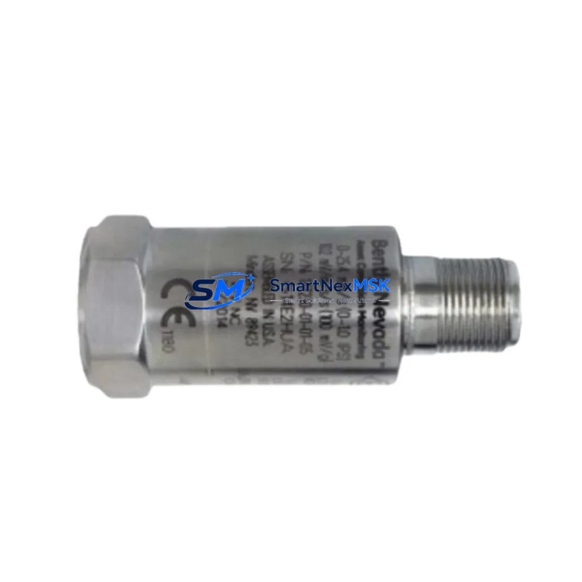
Bently Nevada 190501-23-00-CN Retrofit-Ready Seismic Velocity Transducer for Legacy Control Systems
The Bently Nevada 190501-23-00-CN is a Velomitor CT piezoelectric velocity transducer engineered for high-reliability seismic vibration measurement in rotating machinery protection systems. As a retrofit-ready replacement for discontinued or aging Velomitor CT units, this module integrates directly into existing Bently Nevada 3500 Series machinery protection racks without requiring hardware redesign or software reconfiguration. For facilities managing aging turbine trains, compressor skids, or pump protection panels, the 190501-23-00-CN provides a validated drop-in upgrade path that preserves original wiring topology, signal conditioning parameters, and alarm setpoints.
Industrial sites operating legacy Bently Nevada systems frequently encounter obsolescence challenges when original Velomitor CT transducers reach end-of-service life. The 190501-23-00-CN addresses this directly: it maintains the same 4-pin MIL-spec connector footprint, identical sensitivity output of 100 mV/in/s (4 mV/mm/s), and the same frequency response range of 2 Hz to 1000 Hz, ensuring that existing 3500/20 Rack Interface Module configurations and 3500/42M Proximitor/Seismic Monitor cards continue to operate without parameter changes. Engineers replacing units in the field can retain original Bently Nevada TK-3 armored cable assemblies and junction box terminations, minimizing retrofit labor and eliminating the need for new cable pulls.
Upgrade Compatibility Table
| Parameter | 190501-23-00-CN (This Unit) | Original Velomitor CT | Retrofit Notes |
|---|---|---|---|
| Sensitivity | 100 mV/in/s ± 5% | 100 mV/in/s ± 5% | No recalibration required |
| Frequency Response | 2 Hz – 1000 Hz | 2 Hz – 1000 Hz | Alarm setpoints unchanged |
| Connector Type | 4-pin MIL-C-5015 | 4-pin MIL-C-5015 | Existing cable retained |
| Supply Voltage | 18–30 VDC (loop powered) | 18–30 VDC | No power supply changes |
| Output Signal | 4–20 mA / voltage | 4–20 mA / voltage | Monitor card input unchanged |
| Mounting | Stud mount, 1/4-28 UNF | Stud mount, 1/4-28 UNF | Existing mounting pad reused |
| Communication Compatibility | 3500/42M, 3500/45, 3500/50 | 3500/42M, 3500/45 | Expanded monitor compatibility |
| Replacement Recommendation | Direct drop-in; no firmware update or rack reconfiguration required for standard 3500 Series installations | ||
| Commissioning Focus | Verify OK voltage at monitor card input (typically −10 to −18 VDC); confirm gap voltage within specification after installation | ||
| Warranty | 12-Month Warranty — covers manufacturing defects, signal output deviation, and connector integrity | ||
Retrofit Planning for Existing Automation Systems
Successful integration of the 190501-23-00-CN into a running plant requires systematic pre-installation planning. Before removing the failed transducer, engineers should document the existing OK voltage reading at the 3500/42M Proximitor/Seismic Monitor input and record the current gap voltage if a proximity probe is installed in the same channel group. This baseline ensures that post-installation verification can confirm the replacement unit is operating within the original design envelope.
In installations where the 190501-23-00-CN feeds into a 3500/20 Rack Interface Module alongside other I/O channels — such as a 3500/15 Power Supply Module providing 24 VDC rack power, or a 3500/22M Transient Data Interface capturing waveform data — it is essential to confirm that the rack’s total power budget accommodates the transducer’s loop current draw. Most standard 3500 Series racks with a single 3500/15 or dual redundant 3500/15 power supplies have sufficient headroom, but aging racks with multiple 3500/40M Proximitor Monitor cards and 3500/50 Tachometer Monitor modules should be audited for available current margin before adding or replacing transducers.
Wiring adaptation is straightforward in most cases. The 190501-23-00-CN uses the same color-coded four-conductor shielded cable convention as the original Velomitor CT, and existing Bently Nevada TK-3 armored extension cables can be reused without modification. Terminal block assignments at the junction box and at the 3500 rack I/O module remain identical. For installations using a Bently Nevada 3500/92 Communication Gateway Module to relay vibration data to a DCS or SCADA platform via Modbus TCP or OPC-DA, no protocol reconfiguration is required — the monitor card continues to present the same data register map to the gateway after transducer replacement.
Sites that have migrated their operator interface from a legacy Bently Nevada 1900/65A standalone monitor to a modern System 1 Evolution software platform should verify that the transducer channel configuration in System 1 still reflects the correct transducer type and sensitivity value after replacement. In most cases, the System 1 database entry requires no change, but a channel re-verification step during commissioning is recommended practice. Similarly, if the protection logic is interlocked with a Rockwell Automation ControlLogix or Allen-Bradley PLC via hardwired relay outputs from the 3500 rack, the relay output test should be performed as part of the post-installation functional check to confirm that vibration alarm and danger thresholds trigger correctly.
Downtime Control During System Migration
Minimizing unplanned downtime during a Velomitor CT replacement is achievable with disciplined pre-staging and a structured bypass protocol. Before initiating the physical swap, coordinate with the control room to place the affected monitor channel in bypass mode using the 3500/42M front-panel keyswitch or via System 1 software, preventing a spurious danger trip during the transducer removal and reinstallation window. This bypass should be time-limited and logged in the plant’s permit-to-work system.
The 190501-23-00-CN ships pre-tested and calibrated, with a factory test certificate confirming sensitivity output within ±5% of the rated 100 mV/in/s value. This eliminates the need for on-site calibration equipment and allows the replacement to proceed as a direct swap. Once the new transducer is mounted and the cable reconnected, the commissioning technician should confirm the OK voltage at the monitor card input before releasing the channel from bypass. Typical OK voltage for a healthy Velomitor CT circuit is in the range of −10 to −18 VDC; a reading outside this range indicates a wiring fault or connector issue that must be resolved before the channel is returned to service.
For critical machinery where even a brief bypass window is unacceptable — such as high-speed gas turbines or barrel compressors with API 670 protection requirements — a hot-standby approach using a spare 3500/42M monitor card pre-configured with the replacement transducer parameters allows the channel to be switched over with minimal interruption to the protection system. SMARTNEXMSK maintains in-stock inventory of the 190501-23-00-CN to support emergency dispatch requirements, with same-day shipping available for orders confirmed before the daily cutoff.
Retrofit Support FAQ
Q1: Is the 190501-23-00-CN a direct replacement for all Velomitor CT variants, including the 190501-23-01-CN and 190501-23-02-CN?
A: The 190501-23-00-CN is the standard Velomitor CT configuration and is directly interchangeable with the -00-CN suffix variant. The -01-CN and -02-CN suffix variants differ in cable length or connector orientation; confirm your existing cable assembly length and connector orientation before ordering to ensure a direct fit. SMARTNEXMSK can advise on the correct variant based on your installation drawing or existing part number.
Q2: Do I need to update firmware on the 3500/42M monitor card after installing the 190501-23-00-CN?
A: No firmware update is required. The 3500/42M Proximitor/Seismic Monitor card does not distinguish between original and replacement Velomitor CT units at the firmware level — it reads the analog signal output and compares it against the configured alarm and danger setpoints. Provided the replacement transducer’s sensitivity matches the configured value in the monitor card (100 mV/in/s), no card-level changes are needed.
Q3: What wiring checks should be performed before powering up the replacement transducer?
A: Before applying power, verify continuity on all four conductors between the transducer connector and the monitor card terminal block, confirm shield grounding at the rack end only (single-point ground), and check for any short circuits between conductors or between conductors and shield. After power-up, measure the OK voltage at the monitor card input and confirm it falls within the −10 to −18 VDC OK range before releasing the channel from bypass.
Q4: What does the 12-month warranty cover, and what is the return process?
A: The 12-month warranty covers manufacturing defects, signal output deviation beyond ±5% of rated sensitivity, and connector integrity failures under normal operating conditions. It does not cover damage resulting from incorrect installation, overvoltage, or mechanical impact. To initiate a warranty claim, contact SMARTNEXMSK at [email protected] with your order number, a description of the fault, and the factory test certificate supplied with the unit. Replacement units are dispatched within 3 business days of claim approval.
© 2026 SMARTNEXMSK. All rights reserved.
Original Source: https://smartnexmsk.com
Contact: [email protected] | +86 18259474341



