
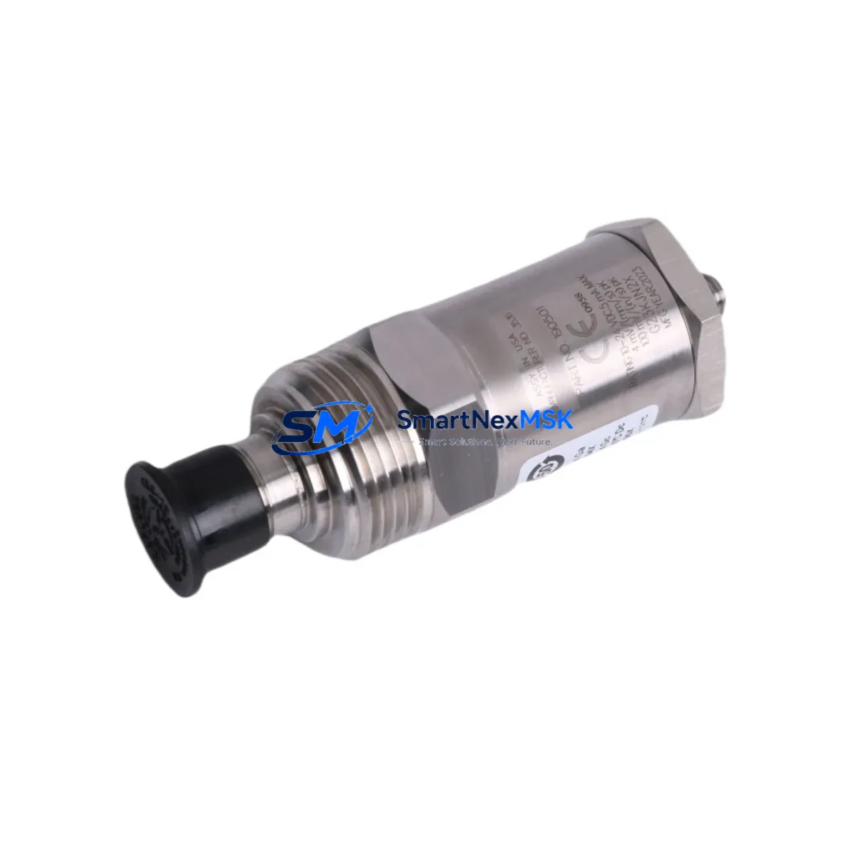
Bently Nevada 190501-99-00-00 Spare Velomitor CT Automation: Spare Replacement & Downtime Risk Control
The Bently Nevada 190501-99-00-00 Velomitor CT is a piezoelectric velocity transducer engineered for continuous vibration monitoring in rotating machinery protection systems. As a maintenance-ready original spare, this unit is stocked and tested to support rapid field replacement within Bently Nevada 3300 and 3500 Series monitoring architectures — minimizing unplanned downtime and preserving system integrity across turbines, compressors, pumps, and gearboxes in critical industrial environments.
For maintenance engineers managing aging machinery protection systems, sourcing a verified original spare for the 190501-99-00-00 is a first-line priority. This Velomitor CT transducer delivers a flat frequency response across its operating range, making it a reliable drop-in replacement for worn or failed units without requiring recalibration of the monitoring rack. Its rugged stainless-steel housing and integral cable design are optimized for harsh plant environments including high-temperature, high-vibration, and chemically aggressive zones.
Procurement engineers will find this unit fully compatible with existing 3500/20 rack power supplies, 3500/42M velocity and acceleration monitor modules, and 3500/22M transient data interface cards — eliminating the risk of cross-compatibility issues during emergency replacement. Each unit ships with full factory test documentation and is covered by a 12-month warranty from date of shipment.
Spare Maintenance Table
| Parameter | Specification |
|---|---|
| Part Number | 190501-99-00-00 |
| Product Family | Velomitor CT Piezoelectric Velocity Transducer |
| Brand | Bently Nevada (Baker Hughes) |
| Compatible Systems | Bently Nevada 3300 Series, 3500 Series Machinery Protection |
| Transducer Type | Piezoelectric velocity (seismic) |
| Sensitivity | 100 mV/in/s (4 mV/mm/s) nominal |
| Frequency Range | 2 Hz – 1,000 Hz (±3 dB) |
| Operating Temperature | -40°C to +121°C (-40°F to +250°F) |
| Housing Material | 316 Stainless Steel |
| Mounting | 1/4-28 UNF threaded stud |
| Cable Length | Integral, application-specific options available |
| Output Connector | MIL-C-5015 style |
| IP Rating | IP67 (dust-tight, water-resistant) |
| Origin | USA |
| Warranty | 12 Months from shipment date |
| Condition | Original, factory-tested |
| Shipping | Tested & inspected before dispatch; global delivery available |
| Maintenance Recommendation | Replace every 3–5 years or upon signal drift/noise anomaly detection |
Maintenance Planning for Continuous Operation
When scheduling a replacement of the 190501-99-00-00 Velomitor CT, a thorough inspection of the surrounding measurement loop and control cabinet is essential to prevent repeat failures and ensure system readiness. Maintenance engineers should begin by verifying the integrity of the Bently Nevada 3500/20 rack power supply module — voltage sag or ripple at the rack level is a common root cause of transducer signal degradation that is often misdiagnosed as a sensor failure.
Next, inspect the field wiring and shielded signal cables connecting the transducer to the 3500/42M velocity monitor card. Damaged cable insulation, improper shield grounding, or corroded MIL-spec connectors can introduce noise that mimics a faulty transducer. If the installation uses a junction box or marshalling panel, check all terminal blocks for oxidation and torque compliance.
The 3500/42M monitor card itself should be inspected for alarm setpoint drift and channel configuration integrity — particularly if the card has been in service for more than five years. In parallel, verify that the 3500/22M transient data interface card is logging correctly and that its communication link to the System 1 software platform is active and error-free.
For installations where the Velomitor CT feeds into a DCS or safety instrumented system via a 4–20 mA signal conditioner or signal isolator, the isolator module should be bench-tested for output accuracy before the new transducer is commissioned. Faulty signal isolators are a frequent source of false alarms post-replacement. Additionally, check any associated relay output modules in the 3500 rack — particularly the 3500/32 relay module — to confirm that trip and alarm relay contacts are clean and within specification.
If the machinery protection system interfaces with an HMI or operator workstation, confirm that the new transducer’s channel is correctly mapped in the display configuration and that historical trend data is being archived without gaps. For older installations running legacy Bently Nevada 3300 Series racks, this replacement is also an appropriate time to assess whether the rack backplane and power distribution board require inspection or replacement as part of a broader system life-extension program.
Site Replacement Workflow
Step 1 — Isolation & Lockout: Follow site LOTO procedures. De-energize the 3500 rack channel associated with the failed transducer. Confirm zero-energy state at the terminal block before disconnecting the field cable.
Step 2 — Physical Removal: Unscrew the 190501-99-00-00 from its mounting stud using the correct torque tool. Inspect the mounting surface for corrosion, thread damage, or contamination. Clean and re-tap if necessary before installing the replacement unit.
Step 3 — Installation: Thread the new Velomitor CT to the manufacturer-specified torque (typically 20–25 in-lb). Route the integral cable away from high-voltage conductors and secure with appropriate cable clamps. Reconnect the MIL-spec connector and verify shield continuity at the rack terminal.
Step 4 — Channel Verification: Re-energize the rack channel. Using the 3500 rack’s front-panel display or System 1 software, confirm that the channel is reading a valid signal within the expected baseline range for the machine at rest. Compare against historical OK values.
Step 5 — Functional Test: Perform a bump test or use a calibrated vibration reference source to verify transducer sensitivity. Confirm alarm and trip setpoints are active and that the relay module responds correctly to a simulated over-limit condition.
Step 6 — Documentation: Record the replacement in the site CMMS, including the new unit’s serial number, installation date, and post-replacement baseline readings. Update the spare parts inventory to trigger reorder of a replacement 190501-99-00-00 for the next maintenance cycle.
Spare Parts Support FAQ
Q1: Is the 190501-99-00-00 a direct drop-in replacement for older Velomitor CT variants?
Yes. The 190501-99-00-00 maintains dimensional and electrical compatibility with earlier Velomitor CT configurations used in 3300 and 3500 Series racks. No rack reconfiguration or setpoint adjustment is required in most standard installations. Always verify the channel configuration in the 3500 rack software before commissioning.
Q2: What is the recommended spare parts stocking strategy for this transducer?
For critical rotating machinery — turbines, compressors, and large pumps — we recommend maintaining a minimum of two units per machine train in on-site inventory. For facilities with multiple 3500 rack installations, a centralized spare pool of 4–6 units is advisable to cover emergency replacement across all monitored assets without waiting for international shipping lead times.
Q3: How is each unit tested before shipment?
Every 190501-99-00-00 unit undergoes electrical continuity verification, sensitivity calibration check, and insulation resistance testing prior to dispatch. Units are shipped with individual test records. Packaging includes anti-static protection and shock-absorbing foam to prevent transit damage.
Q4: What warranty coverage applies and what does it include?
All units carry a 12-month warranty from the date of shipment. The warranty covers manufacturing defects, sensitivity out-of-specification conditions, and connector integrity failures under normal operating conditions. Warranty claims are supported with replacement unit dispatch and return logistics coordination. Units damaged by incorrect installation torque, overvoltage, or chemical exposure are assessed on a case-by-case basis.
© 2026 SMARTNEXMSK. All rights reserved.
Original Source: https://smartnexmsk.com
Contact: [email protected] | +86 18259474341



