
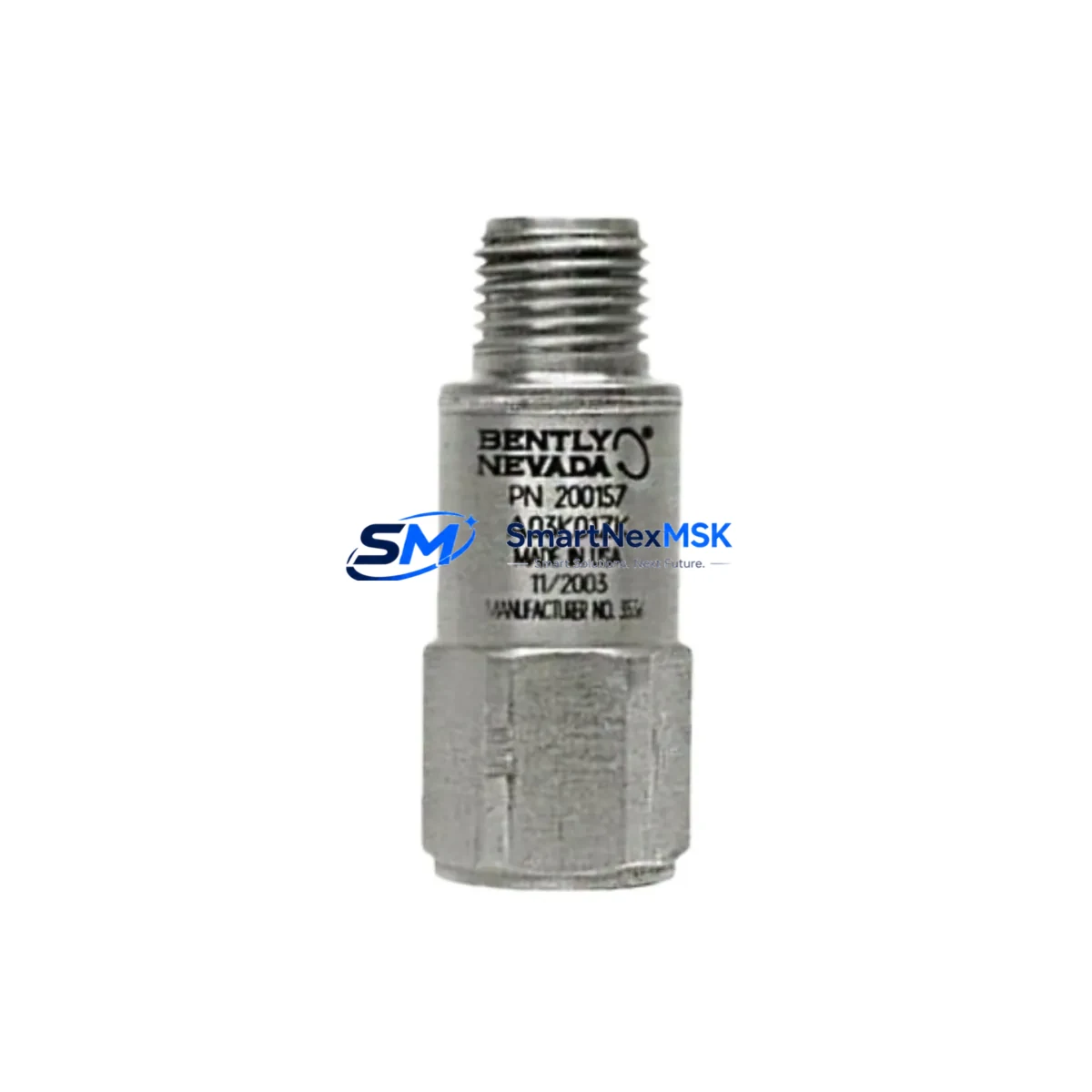
Bently Nevada 200150-08-05 Retrofit-Ready Vibration Sensor for Trendmaster Control Systems
The Bently Nevada 200150-08-05 is a precision accelerometer module engineered for seamless integration into legacy Trendmaster 2000 and Trendmaster Pro condition monitoring platforms. As industrial facilities face increasing pressure to extend the operational life of existing machinery protection systems while managing capital expenditure, the 200150-08-05 provides a verified, drop-in retrofit path that eliminates the need for full system replacement. Whether you are upgrading a single measurement point or overhauling an entire vibration monitoring cabinet, this module delivers the signal fidelity and mechanical compatibility required for mission-critical rotating equipment applications including turbines, compressors, pumps, and motors.
Sourced from authorized distribution channels and subject to full functional verification prior to shipment, each 200150-08-05 unit is tested against Bently Nevada factory specifications. Our inventory is maintained to support urgent replacement scenarios, planned outage windows, and long-term spares programs. A 12-month warranty covers all units against manufacturing defects and functional failure under normal operating conditions.
Upgrade Compatibility Table
| Parameter | Details |
|---|---|
| SKU / Part Number | 200150-08-05 |
| Brand / Manufacturer | Bently Nevada (Baker Hughes) |
| Compatible Platform | Trendmaster 2000, Trendmaster Pro |
| Module Type | Accelerometer / Vibration Sensor |
| Mounting Interface | Standard Trendmaster I/O rack backplane |
| Signal Output | 4–20 mA / IEPE compatible |
| Communication Compatibility | Modbus RTU, proprietary Bently Nevada protocol |
| Replacement Recommendation | Direct drop-in for discontinued 200150 series variants |
| Installation Requirement | No firmware update required for Trendmaster 2000 racks; verify rack slot addressing for Pro series |
| Commissioning Notes | Confirm transducer sensitivity scaling in System 1 software; re-zero baseline after installation |
| Warranty | 12 Months — covers functional failure under normal operating conditions |
Retrofit Planning for Existing Automation Systems
Successful integration of the 200150-08-05 into an existing condition monitoring architecture requires a structured pre-installation review. Begin by auditing the Trendmaster 2000 rack assembly to confirm available slot positions and verify that the I/O backplane revision is compatible with the -08-05 hardware suffix. In multi-rack configurations, the Trendmaster I/O Expansion Rack (3500/20) may be present alongside the primary chassis; ensure that module addressing does not conflict across rack segments.
Power supply capacity is a critical checkpoint. The Trendmaster system power supply module — commonly the 3500/15 Power Supply — must be verified to support the additional current draw of the replacement sensor, particularly in fully populated racks. If the existing power budget is marginal, consider load-shedding non-critical channels or upgrading to a higher-capacity supply before proceeding.
Terminal wiring should be documented before removal of the legacy sensor. The 200150-08-05 uses a standard Bently Nevada terminal block pinout; however, field wiring from the junction box to the rack terminal must be inspected for insulation integrity, shielding continuity, and correct grounding at a single point. Improper grounding is a common source of noise artifacts that can trigger false alarms in the System 1 condition monitoring software.
For facilities running Modbus RTU communication between the Trendmaster rack and a DCS or SCADA layer — such as a Honeywell Experion PKS or Emerson DeltaV system — verify that the register map for the replaced channel remains consistent. If the legacy sensor was mapped to a specific Modbus register block, the replacement module must be configured to the same address to avoid data gaps in the historian or alarm management system. Communication modules such as the Bently Nevada 3500/92 Communication Gateway should be reviewed for any channel-specific configuration that references the replaced sensor.
HMI faceplate updates are often overlooked during sensor replacement. If the plant HMI — whether a Wonderware InTouch panel, FactoryTalk View display, or a custom operator station — references the sensor tag by name or engineering unit, the display configuration should be reviewed to confirm that alarm setpoints, trend scales, and unit labels remain accurate after the swap. This is particularly important when the replacement sensor has a different sensitivity specification than the original, as this will affect the scaling of raw counts to engineering units within the System 1 software or the DCS analog input card.
In systems where the 200150-08-05 feeds into a broader machinery protection chain — alongside proximity probes, velocity transducers, a Keyphasor module, or a temperature input card — the overall protection logic should be reviewed in the 3500 Rack Configuration Software to confirm that voting logic, danger setpoints, and bypass states are correctly preserved after the module swap. A pre-tested spare module held in inventory significantly reduces the risk of extended downtime during an unplanned failure event.
Downtime Control During System Migration
Minimizing production interruption during a sensor replacement or system migration requires a disciplined sequence of pre-outage, outage, and post-outage activities. Before the maintenance window opens, export the full rack configuration from the 3500 Rack Configuration Software and archive the System 1 database snapshot. This ensures that if the replacement introduces unexpected behavior, the original configuration can be restored without relying on memory or incomplete field notes.
During the outage window, place the affected measurement channel in bypass within the machinery protection system before physically removing the legacy sensor. This prevents spurious trips that could affect adjacent equipment or trigger emergency shutdown sequences in the broader control system. After installing the 200150-08-05, perform a bench-level continuity check on the field wiring before re-energizing the rack slot.
Post-installation commissioning should include a live vibration check against a known reference — such as a calibrated shaker or a running machine at a stable load point — to confirm that the replacement sensor is producing a signal within the expected amplitude and frequency range. Compare the live reading against the historical baseline stored in System 1 to validate that the new module is performing equivalently to the original. Once the channel is confirmed healthy, remove the bypass and restore normal protection status. Document the replacement in the plant maintenance management system with the new module serial number, installation date, and commissioning technician sign-off to support future audit and warranty claims.
Retrofit Support FAQ
Q1: Is the 200150-08-05 a direct replacement for other 200150 series part numbers?
The 200150-08-05 is designed as a drop-in replacement for discontinued variants within the 200150 accelerometer family. The -08 designator refers to the cable length and connector configuration, while -05 indicates the sensitivity range. Before ordering, confirm that the original sensor’s sensitivity and connector type match the -08-05 specification. If your existing installation uses a different suffix variant, contact our technical team to verify cross-compatibility.
Q2: What commissioning steps are required after installation?
After physical installation, re-enter the module address in the 3500 Rack Configuration Software if the slot position has changed. Verify transducer sensitivity scaling in System 1 and re-establish the vibration baseline for the monitored machine. Confirm that Modbus register assignments and DCS tag mappings are intact. Perform a functional test by observing live vibration data during a controlled machine run-up before returning the channel to active protection duty.
Q3: How do I verify wiring compatibility before installation?
Compare the terminal block pinout of the 200150-08-05 against the existing field wiring documentation. Check shield termination, ground loop integrity, and cable routing for any sources of electromagnetic interference. If the original installation used a Bently Nevada junction box or field barrier, verify that the barrier’s input impedance is compatible with the replacement sensor’s output characteristics.
Q4: What does the 12-month warranty cover?
All 200150-08-05 units supplied by SMARTNEXMSK carry a 12-month warranty from the date of shipment. The warranty covers functional failure attributable to manufacturing defects or component failure under normal operating conditions as defined by Bently Nevada’s published environmental and electrical specifications. Physical damage, incorrect installation, or operation outside rated parameters are excluded. Warranty claims are processed with return authorization; replacement units are dispatched within 3 business days of claim approval.
© 2026 SMARTNEXMSK. All rights reserved.
Original Source: https://smartnexmsk.com
Contact: [email protected] | +86 18259474341



