
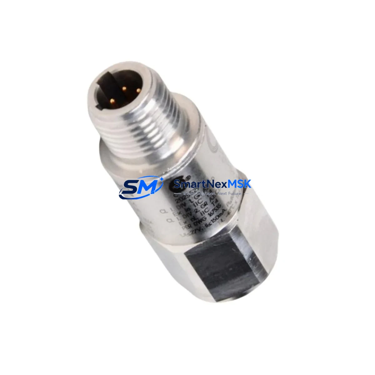
Bently Nevada 200150-09-05 Maintenance-Ready Spare for Trendmaster Pro Automation
The Bently Nevada 200150-09-05 is an original general-purpose accelerometer engineered for continuous vibration monitoring within the Trendmaster Pro distributed monitoring system. For maintenance engineers managing rotating machinery — turbines, compressors, pumps, and fans — this sensor is a critical front-line component in any predictive maintenance or condition-monitoring program. When this accelerometer fails or degrades, the entire vibration data chain is compromised, leaving the control system blind to developing mechanical faults. Stocking a verified replacement unit is not optional; it is a fundamental element of any serious spare parts strategy for facilities running Bently Nevada infrastructure.
The 200150-09-05 mounts directly to machine housings and transmits broadband vibration signals to the Trendmaster Pro I/O module, which processes and routes data to the System 1 condition monitoring software. Its compact, rugged construction is designed for harsh industrial environments including high-temperature, high-humidity, and chemically aggressive atmospheres. Each unit shipped by SMARTNEXMSK is sourced from verified supply channels, electrically tested prior to dispatch, and covered by a 12-month warranty against manufacturing defects.
Spare Maintenance Table
| Parameter | Specification |
|---|---|
| Part Number | 200150-09-05 |
| Brand | Bently Nevada |
| Series | Trendmaster Pro |
| Product Type | General Purpose Accelerometer |
| Measurement | Broadband Vibration (acceleration) |
| Output Signal | Analog voltage, compatible with Trendmaster Pro I/O modules |
| Mounting | Stud or adhesive mount, standard industrial |
| Operating Temperature | -40°C to +120°C |
| Environmental Rating | Suitable for harsh industrial environments (high-temp, high-humidity, chemical exposure) |
| Compatibility | Trendmaster Pro distributed monitoring system; System 1 software |
| Series Compatibility | Trendmaster Pro I/O modules; 3500 series monitoring racks (signal chain) |
| Origin | USA |
| Warranty | 12 Months — manufacturing defects & electrical failures |
| Pre-shipment Test | Yes — electrically tested before dispatch |
| Delivery | Express worldwide shipping available |
| Supply Support | Single-unit emergency orders & multi-unit blanket PO supported |
Maintenance Planning for Continuous Operation
When replacing the 200150-09-05 accelerometer during a planned or emergency maintenance window, a disciplined maintenance engineer treats the sensor swap as an opportunity to audit the entire vibration monitoring loop. Begin by inspecting the Trendmaster Pro I/O module that receives the accelerometer signal — connector corrosion, bent pins, or loose terminal blocks are common causes of intermittent faults that are misdiagnosed as sensor failure. Verify that the I/O module firmware version is current and that the channel configuration in System 1 software matches the replacement sensor’s sensitivity rating.
Check the signal cable and field wiring between the accelerometer and the I/O module. Cable insulation degradation, shield continuity breaks, and improper grounding are frequent sources of noise that corrupt vibration readings. If the cable run passes through conduit near high-voltage drives or motor starters, verify that shielding is intact and grounded at one end only. Inspect all field junction boxes and terminal connections for moisture ingress or oxidation.
The Trendmaster Pro power supply module should be verified for stable output voltage — a sagging or noisy supply rail will introduce measurement errors across all connected sensors. While the cabinet is open, inspect the 24 VDC system power supply and any associated DC/DC converters feeding the monitoring rack. A failing power supply is a common root cause of simultaneous multi-channel anomalies.
For facilities running a mixed Bently Nevada environment, verify the status of any 3300 XL 8mm or 3300 5mm proximity transducer probes monitoring shaft displacement on the same machine train. Accelerometers and proximity probes are complementary — a fault that stresses one sensor type often affects the other measurement plane. Also confirm that the Keyphasor module (if installed) is providing a clean once-per-revolution reference signal, as a degraded Keyphasor signal will corrupt phase-referenced vibration analysis.
Review the Trendmaster Pro communication module and its connection to the plant DCS or historian. A sensor replacement is the right moment to confirm that the new channel is correctly configured, alarm setpoints are active, and trend data is being logged. If the facility uses a Modbus RTU or OPC-DA gateway to bridge Trendmaster Pro data to a third-party SCADA, verify that the gateway tag mapping is intact after the channel is re-enabled. Finally, inspect all DIN rail terminal blocks and signal isolators inside the monitoring cabinet — loose terminals are a leading cause of intermittent sensor faults in high-vibration environments.
Site Replacement Workflow
Step 1 — Verify compatibility. Confirm that the replacement 200150-09-05 matches the original part number on the machine documentation and the Trendmaster Pro channel configuration. Do not substitute a different sensitivity or connector variant without updating the system configuration in System 1.
Step 2 — Isolate and de-energize. Follow site LOTO (Lockout/Tagout) procedures. Disconnect the accelerometer cable at the field junction box before removing the sensor from the machine housing. Confirm zero-energy state before proceeding.
Step 3 — Remove and inspect mounting surface. Clean the mounting pad, check for corrosion or thread damage, and apply fresh thread-locking compound if stud-mounted. A poor mounting surface is the single largest source of high-frequency measurement error and will invalidate baseline readings.
Step 4 — Install and torque. Install the 200150-09-05 to the manufacturer’s specified torque. Over-tightening damages the sensor base; under-tightening introduces resonance artifacts that appear as false alarm conditions in System 1.
Step 5 — Reconnect and verify signal. Reconnect the cable, restore power, and confirm a valid signal in System 1. Check that the channel is reading within the expected baseline range for the machine at normal operating speed. Compare against historical trend data before returning the machine to service.
Step 6 — Update maintenance records. Log the replacement date, new serial number, and post-installation baseline reading in the CMMS. Set a calendar reminder for the next planned inspection interval. Retain the removed unit for failure analysis if root cause investigation is required.
Spare Parts Support FAQ
Q: Is the 200150-09-05 a direct drop-in replacement for older Trendmaster Pro accelerometer variants?
A: Yes, the 200150-09-05 is designed as a direct replacement within the Trendmaster Pro monitoring system. Always verify the connector type and cable pinout against your existing field wiring before installation. If your system uses an earlier cable assembly, a field-wiring adapter may be required. Contact our technical team for pinout confirmation before ordering.
Q: What does the 12-month warranty cover, and what is excluded?
A: The 12-month warranty covers manufacturing defects and electrical failures under normal operating conditions. Each unit is electrically tested before shipment. Physical damage caused by incorrect installation, over-torquing, mounting surface contamination, or exposure beyond rated environmental limits is not covered. Warranty claims require the original order reference and a brief fault description.
Q: How should spare accelerometers be stored to maximize shelf life and readiness?
A: Store in original packaging in a dry, temperature-controlled environment (10°C–30°C, <70% RH). Avoid storage near strong magnetic fields or vibration sources. Inspect the connector and cable termination annually. Replace desiccant packs in the storage container if ambient humidity is a concern. Units stored correctly remain deployment-ready for 3–5 years.
Q: Can SMARTNEXMSK supply multiple units for a blanket MRO spare parts order?
A: Yes. We support single-unit emergency orders and multi-unit blanket purchase orders for MRO inventory programs. Volume pricing, confirmed lead times, and consolidated shipping options are available. Contact our team with your required quantity and delivery schedule for a formal quotation.
© 2026 SMARTNEXMSK. All rights reserved.
Original Source: https://smartnexmsk.com
Contact: [email protected] | +86 18259474341



