
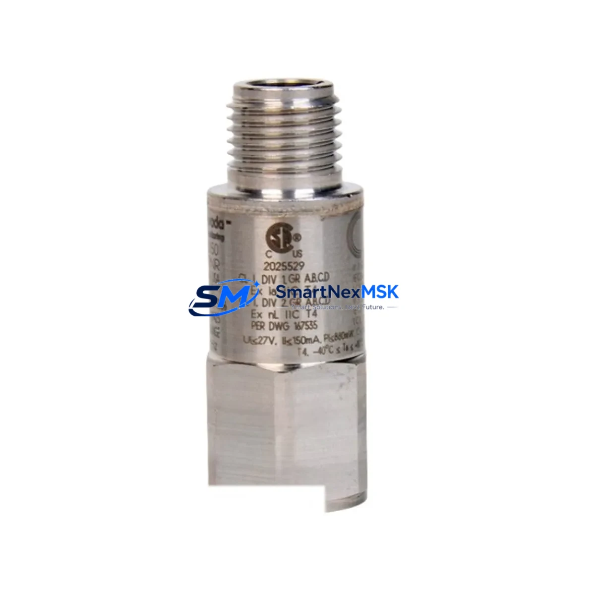
Bently Nevada 200155-02-05 Maintenance-Ready Spare for TrendMaster Pro Automation
The Bently Nevada 200155-02-05 is an original low-frequency accelerometer designed for the TrendMaster Pro continuous monitoring system. In rotating machinery environments — turbines, compressors, pumps, fans, and gearboxes — this sensor is a critical front-line component for vibration data acquisition. When this unit fails or degrades, the entire condition monitoring loop is compromised, leaving maintenance engineers blind to developing faults. Sourcing a verified, original replacement is the fastest path to restoring full system visibility and preventing unplanned downtime.
For maintenance engineers managing aging TrendMaster Pro installations, the 200155-02-05 represents a direct, drop-in replacement that preserves signal integrity and system calibration. For procurement engineers, it is a high-priority spare that belongs in every rotating machinery maintenance kit. This unit ships tested, with a 12-month warranty, and is supported by long-term supply continuity for legacy system sustainment.
Spare Maintenance Table
| Parameter | Specification / Detail |
|---|---|
| Part Number / SKU | 200155-02-05 |
| Brand | Bently Nevada |
| Series | TrendMaster Pro |
| Product Type | Low-Frequency Accelerometer / Vibration Sensor |
| Application | Rotating machinery condition monitoring — turbines, compressors, pumps, fans, gearboxes |
| Signal Output | 4–20 mA (loop-powered, compatible with TrendMaster Pro I/O modules) |
| Frequency Range | Low-frequency vibration (suitable for slow-speed and variable-speed machinery) |
| Mounting | Stud-mount or adhesive mount per installation standard |
| Connector / Interface | Compatible with Bently Nevada TrendMaster Pro field wiring and terminal blocks |
| Operating Environment | Industrial — suitable for high-vibration, high-temperature plant environments |
| Origin | USA (Original Bently Nevada / Baker Hughes) |
| Compatibility | TrendMaster Pro monitoring system; direct replacement for 200155-02-05 |
| Condition | New / Original — tested before shipment |
| Warranty | 12 Months |
| Lead Time | In stock — ships within 1–3 business days |
Maintenance Planning for Continuous Operation
When replacing the 200155-02-05 accelerometer in a TrendMaster Pro installation, a thorough site inspection should extend beyond the sensor itself. Maintenance engineers should simultaneously verify the condition of the TrendMaster Pro I/O module (such as the 3500/42M or equivalent TrendMaster Pro I/O card) that receives the 4–20 mA signal, as a degraded input channel can mask sensor faults or produce erroneous readings even after a sensor swap.
The field wiring from the sensor to the junction box and back to the monitoring rack should be inspected for insulation damage, moisture ingress, and terminal corrosion — particularly in high-vibration or outdoor installations. Terminal blocks and cable glands at the junction box are common failure points that are frequently overlooked during sensor-only replacements. The TrendMaster Pro power supply module should be load-tested to confirm it is delivering stable voltage to the sensor loop; an under-voltage condition will cause the 200155-02-05 to report out-of-range values even when the sensor is healthy.
For installations where the TrendMaster Pro system feeds data to a DCS or SCADA platform via a Modbus or OPC gateway, the communication module and its configuration should be verified after any sensor replacement to confirm that channel mapping and alarm setpoints remain intact. If the plant uses a Bently Nevada 3500 rack alongside TrendMaster Pro for complementary monitoring, the 3500 series proximity probe drivers, I/O modules, and communication gateway cards should be included in the same inspection cycle.
Signal isolators or barriers installed between the sensor and the monitoring system — particularly in hazardous area (ATEX/IECEx) installations — should be tested for correct pass-through and isolation resistance. Fuse holders and fuses in the sensor power circuit are low-cost items that are often the root cause of apparent sensor failures and should be replaced as a matter of course during any corrective maintenance event. Where HMI panels display TrendMaster Pro vibration trends, the HMI communication link and display configuration should be confirmed operational after the sensor is reinstated.
Building a structured spare parts kit around the 200155-02-05 — including at least one spare I/O module, a set of terminal blocks, a replacement power supply fuse set, and a spare communication module — is the most effective strategy for minimizing mean time to repair (MTTR) on TrendMaster Pro-monitored assets.
Site Replacement Workflow
Step 1 — Isolation and Permit: Obtain a safe work permit and isolate the sensor loop at the junction box. Do not de-energize the TrendMaster Pro rack unless required by site procedure — most sensor replacements can be performed with the monitoring system live, allowing immediate verification of the replacement.
Step 2 — Physical Removal: Disconnect the field cable at the sensor connector. Remove the 200155-02-05 from its mounting stud or adhesive pad. Inspect the mounting surface for corrosion, thread damage, or contamination and clean as required before installing the replacement.
Step 3 — Installation: Install the replacement 200155-02-05 to the manufacturer’s specified torque (stud mount) or adhesive cure time. Reconnect the field cable, ensuring correct polarity on the 4–20 mA loop. Verify that the cable shield is grounded at one end only, per Bently Nevada field wiring guidelines.
Step 4 — Verification: At the TrendMaster Pro workstation or DCS display, confirm that the channel is reading a valid vibration value within the expected baseline range for the machine at its current operating condition. Compare against historical trend data to confirm the replacement sensor is performing consistently with the previous unit.
Step 5 — Documentation: Record the replacement in the CMMS, update the spare parts inventory, and schedule the next planned inspection interval. If the failed sensor shows signs of premature wear, initiate a root cause review to determine whether mounting, wiring, or process conditions contributed to the failure.
This workflow applies equally to planned maintenance replacements and emergency corrective actions. Having the 200155-02-05 in stock eliminates the procurement lead time from the critical path and reduces total downtime to the time required for physical replacement and verification — typically under two hours for an experienced technician.
Spare Parts Support FAQ
Q1: Is the 200155-02-05 a direct replacement for all TrendMaster Pro accelerometer channels?
The 200155-02-05 is a low-frequency accelerometer variant within the TrendMaster Pro sensor family. It is a direct replacement for channels configured for low-frequency vibration measurement. Before installation, confirm that the replacement sensor suffix (-02-05) matches the original unit’s configuration, as different suffix codes indicate different sensitivity ranges and connector types. If the original sensor suffix differs, contact our technical team for compatibility confirmation before installation.
Q2: What is included in the 12-month warranty and how does it apply to field-installed units?
The 12-month warranty covers manufacturing defects and premature failure under normal operating conditions from the date of shipment. Each unit is functionally tested prior to dispatch. The warranty does not cover damage resulting from incorrect installation, over-range mechanical shock, or chemical contamination. In the event of a warranty claim, we provide a replacement unit and support the return logistics process.
Q3: Can you supply the 200155-02-05 for long-term or blanket purchase orders to support ongoing maintenance programs?
Yes. We support long-term supply agreements for maintenance programs requiring regular replenishment of TrendMaster Pro spare parts. Blanket orders with scheduled releases are available, and we maintain buffer stock specifically for legacy Bently Nevada components to protect against manufacturer discontinuation risk. Contact our sales team to discuss volume pricing and delivery scheduling.
Q4: How is the unit tested and packaged before shipment?
Each 200155-02-05 unit undergoes functional output verification and physical inspection before packaging. Units are shipped in anti-static, shock-protected packaging with a test record. For international shipments, export documentation including commercial invoice, packing list, and country of origin certificate is provided as standard.
© 2026 SMARTNEXMSK. All rights reserved.
Original Source: https://smartnexmsk.com
Contact: [email protected] | +86 18259474341



