
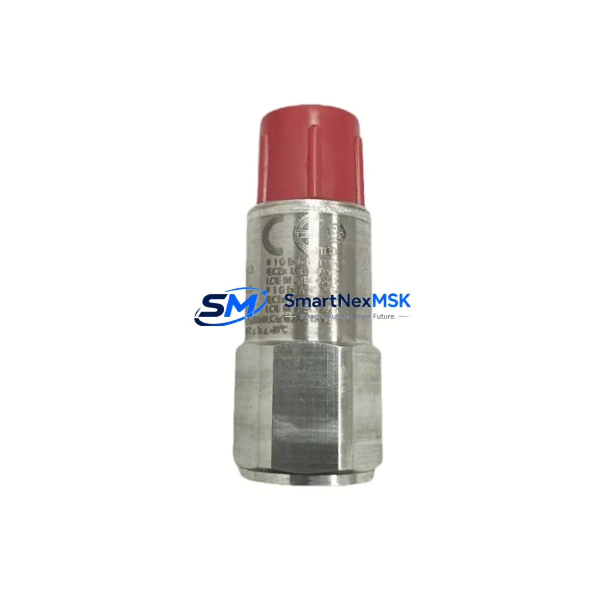
Bently Nevada 200155-15-CN Retrofit-Ready Accelerometer for Trendmaster Pro Control Systems
The Bently Nevada 200155-15-CN is a low-frequency accelerometer engineered for the Trendmaster Pro continuous machinery monitoring platform. As legacy vibration monitoring infrastructure ages across petrochemical, power generation, and rotating equipment facilities, the 200155-15-CN has become a critical retrofit component for engineers tasked with sustaining measurement accuracy without replacing the entire monitoring architecture. This unit delivers reliable low-frequency vibration data to the Trendmaster Pro data manager, maintaining signal integrity across long cable runs and harsh industrial environments.
Whether you are replacing a failed sensor on an operating compressor train, upgrading a turbine monitoring cabinet, or restoring a mothballed production line, the 200155-15-CN integrates directly into existing Trendmaster Pro wiring infrastructure. Each unit shipped by SMARTNEXMSK is function-tested prior to dispatch, with a 12-month warranty covering manufacturing defects and performance deviation from published specifications.
Upgrade Compatibility Table
| Parameter | Detail |
|---|---|
| SKU / Part Number | 200155-15-CN |
| Brand | Bently Nevada |
| Series | Trendmaster Pro |
| Sensor Type | Low-Frequency Accelerometer (ICP-compatible) |
| Mounting Interface | Stud-mount, compatible with standard Trendmaster Pro transducer wiring harness |
| Signal Output | 4–20 mA / voltage output compatible with Trendmaster Pro I/O modules |
| Communication Compatibility | Trendmaster Pro Data Manager (3500/22M, 3500/42M signal conditioning) |
| Replacement For | Discontinued Bently Nevada low-frequency accelerometer variants in Trendmaster Pro installations |
| Installation Requirement | Verify cable shield continuity; confirm I/O channel address in Trendmaster Pro configuration software |
| Commissioning Note | Re-zero baseline after installation; validate alarm setpoints in System 1 or Trendmaster Pro operator interface |
| Warranty | 12 Months — covers manufacturing defects and out-of-spec performance |
Retrofit Planning for Existing Automation Systems
Retrofitting the 200155-15-CN into an active Trendmaster Pro monitoring system requires a structured approach to avoid measurement gaps or false alarms during the changeover. Begin by auditing the existing transducer wiring from the sensor mounting point back to the Trendmaster Pro I/O module — typically a 3500/22M Transient Data Interface or a 3500/42M Proximitor/Seismic Monitor card installed in the 3500 rack. Confirm that the cable type, shield grounding scheme, and connector pinout match the 200155-15-CN specification sheet before disconnecting the legacy sensor.
In many aging installations, the Trendmaster Pro Data Manager will be running firmware that predates current System 1 software releases. Before replacing the accelerometer, verify that the channel configuration in the data manager correctly reflects the sensor sensitivity (mV/g), frequency range, and measurement units. If the system is integrated with a Bently Nevada 3500 rack, check the rack’s I/O module addressing to ensure the replacement sensor is recognized on the correct channel without requiring a full rack reconfiguration.
For facilities running parallel monitoring on critical assets such as steam turbines, centrifugal compressors, or large induction motors, it is common to find the Trendmaster Pro system co-located with a Bently Nevada 3300 XL proximitor for shaft displacement measurement and a 3500/15 Power Supply module providing conditioned DC power to the rack. Confirm that the power budget of the existing supply can accommodate the 200155-15-CN without exceeding the rated output current of the 3500/15 or its redundant companion.
Wiring adaptation is frequently required when the original sensor used a different connector body or cable jacket specification. In these cases, a Bently Nevada 330130 extension cable or equivalent field-wiring adapter may be needed to bridge the terminal block in the junction box to the new sensor. Ensure all cable entries maintain the IP rating of the enclosure and that the shield drain wire is terminated at one end only to prevent ground loops that would corrupt the vibration signal.
If the retrofit is part of a broader control cabinet upgrade that includes replacing a legacy Trendmaster Pro 2000 Series wiring module with a current-generation I/O interface, coordinate the sensor replacement with the wiring module swap to minimize the number of separate outages required. In some plant configurations, the Trendmaster Pro system feeds vibration data to a DCS historian via Modbus RTU or OPC-DA — verify that the tag mapping and engineering unit scaling remain consistent after the sensor swap to avoid corrupting trend data in the process historian.
For sites where the Trendmaster Pro is integrated with an HMI panel running Wonderware InTouch or a Bently Nevada operator display, update the sensor tag descriptor and alarm limits in the HMI configuration after commissioning the 200155-15-CN. This prevents operators from responding to stale baseline alarms that no longer reflect the calibrated output of the new sensor.
Downtime Control During System Migration
Minimizing unplanned downtime during a sensor retrofit on a live Trendmaster Pro system requires pre-staging all replacement components — including the 200155-15-CN accelerometer, any required extension cables, terminal adapters, and a calibrated reference instrument — before the maintenance window opens. Where the asset monitoring configuration allows, place the affected channel into bypass mode within the Trendmaster Pro data manager to suppress spurious alarms during the physical swap without disabling protection on adjacent channels.
Back up the full Trendmaster Pro channel configuration, alarm setpoints, and trend history to a portable storage device before beginning any wiring work. This ensures that if the data manager requires a channel reset during sensor recognition, the original configuration can be restored in minutes rather than hours. For critical rotating equipment where continuous vibration monitoring is a safety requirement, coordinate with the control room to confirm that the DCS or safety instrumented system (SIS) has acknowledged the bypass and that a qualified operator is stationed at the local panel for the duration of the swap.
After installing the 200155-15-CN and restoring wiring, perform a bench-level signal check using a portable vibration calibrator before re-enabling the channel in the Trendmaster Pro system. Confirm that the live reading matches the expected baseline for the machine at its current operating speed and load. Once validated, remove the bypass, restore alarm setpoints, and document the as-found and as-left vibration readings in the plant maintenance management system (CMMS) to establish a new baseline for trend analysis.
Retrofit Support FAQ
Q1: Is the 200155-15-CN a direct drop-in replacement for the original Trendmaster Pro low-frequency accelerometer?
In most Trendmaster Pro installations, the 200155-15-CN is a functional replacement for the original low-frequency accelerometer variant. Verify the sensitivity specification (mV/g) and frequency range against your existing channel configuration in the Trendmaster Pro data manager before installation. Minor sensitivity differences may require a scaling adjustment in the channel setup.
Q2: What wiring checks are required before connecting the 200155-15-CN?
Confirm cable continuity, shield integrity, and correct polarity at the terminal block. Verify that the junction box connector pinout matches the 200155-15-CN wiring diagram. Check that the cable shield is grounded at the data manager end only. Inspect the cable jacket for damage that could introduce noise into the signal path.
Q3: How do I verify compatibility with my existing 3500 rack and Trendmaster Pro data manager?
Cross-reference the 200155-15-CN part number against the Trendmaster Pro transducer compatibility list in your system documentation. Confirm the I/O module type (e.g., 3500/42M) supports the sensor output format. If your data manager firmware is older than the current release, contact SMARTNEXMSK for compatibility guidance before ordering.
Q4: What does the 12-month warranty cover, and how is it claimed?
The 12-month warranty covers manufacturing defects and performance deviation from the published specification under normal operating conditions. To claim warranty service, contact SMARTNEXMSK with the original order reference, a description of the fault, and the as-found measurement data. Units confirmed defective will be replaced or credited at SMARTNEXMSK’s discretion.
© 2026 SMARTNEXMSK. All rights reserved.
Original Source: https://smartnexmsk.com
Contact: [email protected] | +86 18259474341



