
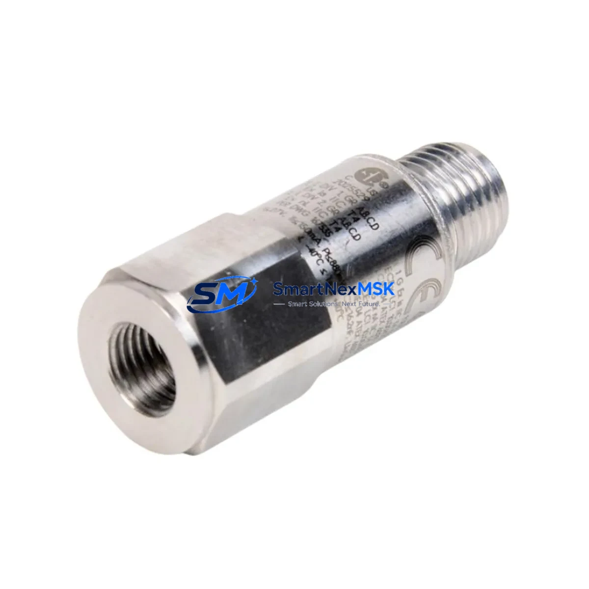
Bently Nevada 200157-15-05 Retrofit-Ready Enveloping Accelerometer for TrendMaster Pro Control Systems
The Bently Nevada 200157-15-05 is a high-reliability enveloping accelerometer engineered for seamless integration into legacy TrendMaster Pro continuous machinery monitoring systems. As industrial facilities face increasing pressure to extend the operational life of existing condition monitoring infrastructure while managing capital expenditure, the 200157-15-05 provides a validated, drop-in retrofit path that eliminates the need for full system replacement. Whether you are recovering from a sensor failure on a critical rotating asset, upgrading a deteriorating field wiring harness, or migrating from an end-of-life monitoring node, this accelerometer delivers the signal fidelity and mechanical compatibility required to restore full system functionality with minimal downtime.
Designed to interface directly with the TrendMaster Pro 3500 Series monitoring framework, the 200157-15-05 maintains full compatibility with the existing Dynamic Pressure Measurement (DPM) signal conditioning architecture. Engineers performing a retrofit should verify the sensor’s frequency response range against the original channel configuration stored in the System 1 software database, ensuring that alarm setpoints, full-scale ranges, and transducer type assignments remain consistent after the swap. The sensor’s 4-pin MIL-spec connector mates with standard TrendMaster Pro field wiring without adapter modification, preserving the integrity of the existing cable run from the junction box to the monitoring rack.
Before installation, technicians should confirm that the local power supply module — typically a TrendMaster Pro 3500/15 Power Supply or equivalent rack-mounted unit — can sustain the additional current draw if multiple sensors are being replaced simultaneously during a planned outage window. The 200157-15-05 operates within the standard IEPE (Integrated Electronics Piezo-Electric) excitation range, drawing constant current from the signal conditioner input card. If the existing 3500/20 Rack Interface Module or 3500/22M Transient Data Interface is being retained, no firmware changes are required for single-sensor substitution.
For facilities executing a broader control system modernization — for example, migrating from a standalone TrendMaster Pro rack to a networked 3500 Series platform with Modbus TCP or OPC-UA connectivity — the 200157-15-05 remains fully compatible with the upgraded I/O infrastructure. The sensor output is analog and protocol-agnostic at the field level, meaning the communication migration burden falls entirely on the rack-level interface cards rather than the transducer itself. This makes the 200157-15-05 an ideal anchor component during phased upgrades where the field sensor layer is stabilized first, followed by incremental rack and software modernization.
Facilities managing mixed-vintage monitoring environments — where some assets run on TrendMaster Pro nodes while others have already been migrated to 3500/40M Proximitor/Seismic Monitor cards — will find that the 200157-15-05 bridges both environments without requiring parallel wiring schemes. The sensor’s output characteristics are consistent with Bently Nevada’s published transducer specifications, ensuring that System 1 Evolution software can ingest data from both legacy and modernized rack configurations within a single plant historian instance.
Upgrade Compatibility Table
| Parameter | Detail |
|---|---|
| SKU / Part Number | 200157-15-05 |
| Compatible Platform | Bently Nevada TrendMaster Pro, 3500 Series |
| Sensor Type | Enveloping Accelerometer (IEPE) |
| Connector Interface | 4-pin MIL-spec, mates with standard TrendMaster Pro field wiring |
| Signal Conditioning | Compatible with 3500/20 Rack Interface Module, 3500/22M Transient Data Interface |
| Communication Compatibility | Analog output; rack-level Modbus TCP / OPC-UA migration supported |
| Power Requirement | IEPE constant-current excitation from signal conditioner input card |
| Installation Requirement | Direct mount; no adapter required for standard TrendMaster Pro cable runs |
| Software Compatibility | System 1 Evolution; alarm setpoints and transducer type must be verified post-swap |
| Replacement Recommendation | Drop-in replacement; verify channel configuration and full-scale range before restart |
| Commissioning Focus | Confirm IEPE excitation current, sensor sensitivity, and alarm threshold alignment |
| Warranty | 12-Month Warranty — covers manufacturing defects and functional performance |
Retrofit Planning for Existing Automation Systems
A successful retrofit begins well before the maintenance window opens. The first step is a full audit of the existing TrendMaster Pro rack configuration, documenting each occupied slot, the assigned transducer type for every channel, and the current alarm and alert setpoints stored in the System 1 database. For facilities where the original commissioning documentation has been lost, this audit can be performed non-intrusively by exporting the channel configuration report directly from System 1 Evolution while the system remains online.
The physical installation of the 200157-15-05 requires access to the sensor mounting pad on the machine casing, which should be inspected for corrosion, thread damage, or surface irregularities before the new sensor is torqued into position. The field cable — typically a low-noise coaxial or twisted-pair run terminated at a TrendMaster Pro junction box — should be tested for continuity and insulation resistance before reconnection. If the cable run exceeds the manufacturer’s recommended length for IEPE signal integrity, a signal conditioner or in-line buffer may be required to prevent signal degradation at the rack input.
At the rack level, the 3500/20 Rack Interface Module handles the IEPE excitation and signal conditioning for accelerometer inputs. If the rack also hosts 3500/42M Proximitor/Seismic Monitor cards for proximity probe channels, or 3500/45 Position Monitor cards for axial position measurement, these adjacent modules should be inspected for firmware currency as part of the broader retrofit scope. Similarly, if the facility uses a 3500/92 Communication Gateway Module for Modbus or Ethernet/IP connectivity to the plant DCS or SCADA layer, the gateway configuration should be backed up before any rack-level work begins.
For facilities that also operate Bently Nevada 3300 Series proximity systems on adjacent machinery trains, the retrofit plan should account for the possibility that the 3300 XL 8mm Proximity Transducer System field wiring shares conduit runs with the TrendMaster Pro accelerometer cables. Separation and labeling of these cable runs during the retrofit prevents cross-identification errors during recommissioning. If the plant historian — whether OSIsoft PI, Wonderware, or an equivalent SCADA platform — is configured to receive data from both the TrendMaster Pro nodes and the 3500 Series rack via OPC-DA or OPC-UA, the data source tags for the replaced sensor channel should be verified in the historian configuration after the retrofit is complete.
HMI screens that display vibration trend data for the affected machine train should be reviewed to confirm that the engineering unit scaling, alarm color thresholds, and trend history display windows remain correctly mapped to the updated channel after the sensor swap. If the facility uses a Bently Nevada 3500/94 Ethernet Transient Data Interface for high-speed waveform capture, the transient data buffer configuration for the affected channel should also be verified post-installation.
Downtime Control During System Migration
Minimizing unplanned downtime during a sensor retrofit requires a structured pre-outage preparation protocol. Before the maintenance window begins, the existing sensor channel should be placed in bypass mode within System 1 to prevent spurious alarms from triggering automatic shutdown sequences during the physical swap. The bypass should be documented in the plant’s permit-to-work system, with a defined time limit that matches the planned maintenance window duration.
The original program logic stored in the System 1 database — including the transducer type assignment, full-scale range, alarm setpoints, and alert delay timers — should be exported and saved to a secure backup location before any rack-level changes are made. This backup serves as the restoration baseline if the retrofit encounters unexpected compatibility issues that require the original sensor to be temporarily reinstalled.
During the physical swap, the machine train should remain in a controlled shutdown state with the main drive isolated and locked out in accordance with the facility’s LOTO (Lockout/Tagout) procedure. The 200157-15-05 can typically be installed and the field cable reconnected within a single shift, provided that the mounting surface preparation and cable continuity testing have been completed in advance. After installation, the sensor channel should be brought out of bypass mode incrementally — first verifying the raw IEPE signal at the rack input using a portable signal analyzer, then confirming the System 1 channel reading against a known reference before the machine is restarted.
Post-restart, the first 30 minutes of operation should be monitored closely for any deviation in the vibration trend baseline compared to the pre-retrofit historical data. If the new sensor’s sensitivity or mounting orientation differs slightly from the original, a short-term alarm setpoint relaxation may be appropriate during the initial run-in period, with setpoints restored to their original values after the baseline is confirmed stable. All retrofit activities, including the pre-outage bypass, physical installation, post-installation verification, and setpoint restoration, should be documented in the plant’s maintenance management system for future reference.
Retrofit Support FAQ
Q: Is the 200157-15-05 a direct drop-in replacement for the original TrendMaster Pro enveloping accelerometer?
A: Yes. The 200157-15-05 is designed as a direct mechanical and electrical replacement for the original TrendMaster Pro enveloping accelerometer. The 4-pin MIL-spec connector, mounting thread, and IEPE signal output are compatible with the existing field wiring and rack input card without modification. After installation, the System 1 channel configuration should be verified to confirm that the transducer type assignment and full-scale range match the new sensor’s published specifications.
Q: What commissioning steps are required after installing the 200157-15-05?
A: After physical installation and cable reconnection, the technician should verify the IEPE excitation current at the rack input, confirm the raw sensor signal using a portable analyzer, and compare the System 1 channel reading against a known reference. Alarm setpoints, alert delay timers, and full-scale range settings should be reviewed and adjusted if necessary before the machine is restarted. The channel bypass should be removed only after the signal has been confirmed stable.
Q: Can the 200157-15-05 be used in a system that is being migrated from TrendMaster Pro to the 3500 Series platform?
A: Yes. The 200157-15-05’s analog IEPE output is compatible with both TrendMaster Pro signal conditioning and 3500 Series input cards, including the 3500/40M Proximitor/Seismic Monitor. This makes it suitable for phased migration projects where the field sensor layer is stabilized before the rack and software infrastructure is upgraded.
Q: What does the 12-month warranty cover?
A: The 12-month warranty covers manufacturing defects and functional performance failures under normal operating conditions. Each unit undergoes pre-shipment functional testing to verify signal output, connector integrity, and mechanical assembly before dispatch. Warranty claims should be submitted to [email protected] with the original order reference and a description of the observed fault.
© 2026 SMARTNEXMSK. All rights reserved.
Original Source: https://smartnexmsk.com
Contact: [email protected] | +86 18259474341



