
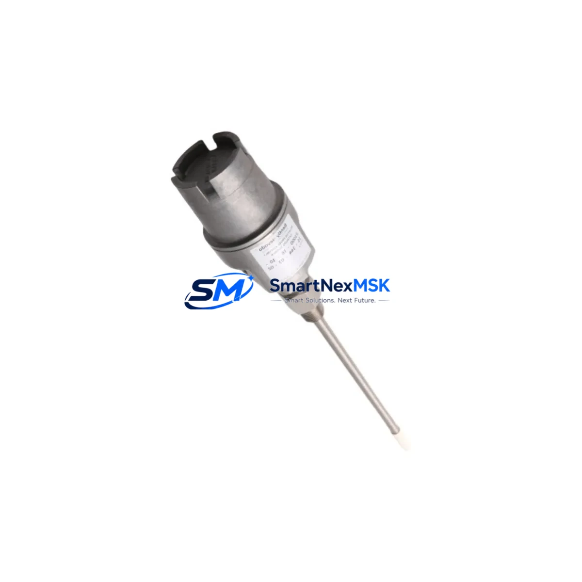
Bently Nevada 21000-16-05-00-050-03-02 Retrofit-Ready Monitor for 21000 Series Control Systems
The Bently Nevada 21000-16-05-00-050-03-02 is a proximity transducer monitor engineered for seamless integration into legacy 21000 Series vibration monitoring systems. As original 21000 Series hardware reaches end-of-life and spare parts become increasingly scarce, this module provides a verified, drop-in compatible replacement path that preserves existing wiring infrastructure, signal conditioning logic, and rack architecture — minimizing retrofit risk and reducing total project cost.
Industrial facilities operating rotating machinery — including turbines, compressors, pumps, and gearboxes — rely on continuous vibration and position monitoring to prevent catastrophic failure. When a 21000 Series monitor fails or becomes obsolete, the replacement must match the original channel configuration, power supply requirements, and output signal range precisely. The 21000-16-05-00-050-03-02 meets these requirements, supporting direct substitution without requiring panel rewiring or software re-engineering in most standard installations.
Upgrade Compatibility Table
| Parameter | Detail |
|---|---|
| SKU / Part Number | 21000-16-05-00-050-03-02 |
| Series Compatibility | Bently Nevada 21000 Series |
| Module Function | Proximity Transducer Monitor |
| Installation Type | Rack-mount, backplane interface |
| Communication Compatibility | Compatible with existing 21000 Series rack communication bus |
| Terminal Wiring | Direct terminal-for-terminal replacement in standard 21000 Series enclosures |
| Power Supply Requirement | Verify rack power module (e.g. 21000-01 or equivalent) output capacity before installation |
| Replacement Recommendation | Suitable for direct swap; confirm channel address and jumper settings prior to commissioning |
| Commissioning Focus | Gap voltage verification, OK relay output check, Keyphasor signal alignment |
| Warranty | 12 Months — covers manufacturing defects and functional failure under normal operating conditions |
Retrofit Planning for Existing Automation Systems
Successful retrofit of the 21000-16-05-00-050-03-02 into an operating plant environment requires systematic pre-installation planning. Before removing the failed or obsolete monitor, engineers should document the existing terminal wiring layout, confirm the rack slot address, and verify that the system’s power supply module — typically a dedicated 21000 Series power conditioner — can sustain the load of the replacement unit alongside other installed monitors.
In multi-channel monitoring racks, the 21000-16-05-00-050-03-02 typically operates alongside complementary modules such as the Bently Nevada 21000-01 power supply, 21000-02 rack interface module, and channel-specific monitors for axial position, differential expansion, and speed. Where Keyphasor signals are used for phase reference, the Bently Nevada 3500/25 Keyphasor module or equivalent 21000 Series Keyphasor input card must remain correctly configured to avoid triggering false OK relay trips during the changeover.
For facilities integrating the 21000 Series rack into a broader DCS or safety instrumented system, confirm that the 4–20 mA output signals from the replacement monitor are correctly scaled and mapped at the receiving controller — whether a Honeywell TDC 3000, Emerson DeltaV, or Yokogawa CENTUM VP. Where the existing system uses a Bently Nevada 3500 Series rack in parallel for redundancy, ensure that the 3500/42M or 3500/45 vibration monitors on the redundant path are not affected by the 21000 Series swap.
Terminal block adapters and field wiring should be inspected for insulation degradation, particularly in high-temperature or high-humidity environments. If the original installation used Bently Nevada 330130 or 330180 series proximity probes with extension cables, verify that probe gap settings remain within the linear range specified for the 21000-16-05-00-050-03-02 input circuit. Recalibration of gap voltage at the field probe location is recommended after module replacement to confirm measurement accuracy before returning the machine to service.
Downtime Control During System Migration
Minimizing unplanned downtime during a 21000 Series monitor replacement requires a structured hot-swap or planned-outage strategy. Where the process permits a brief controlled shutdown, the preferred approach is to isolate the affected monitoring channel, document all OK relay states and alarm setpoints from the existing configuration, and perform a like-for-like module swap within a single maintenance window.
Before powering down the rack, export or photograph all channel configuration parameters — including full-scale range, alert and danger setpoints, time delay settings, and transducer type selection. If the plant uses a System 1 condition monitoring software platform connected to the 21000 Series rack, ensure that the historian is set to record the last known values and that the communication link to the monitoring workstation is re-established and verified after the replacement module is seated and powered.
For critical machinery where continuous monitoring is mandatory, a temporary portable vibration analyzer — such as a Bently Nevada ADRE 408 or equivalent — can be connected to the field probe terminals to maintain surveillance during the module changeover interval. This approach protects against undetected machinery excursions while the permanent monitor is offline, and provides a baseline vibration signature for comparison after the 21000-16-05-00-050-03-02 is commissioned.
All replacement modules supplied by SMARTNEXMSK are function-tested prior to shipment. Each unit undergoes output signal verification, OK relay actuation testing, and power consumption measurement to confirm compliance with 21000 Series specifications before dispatch.
Retrofit Support FAQ
Q: Is the 21000-16-05-00-050-03-02 a direct replacement for my existing 21000 Series monitor?
A: In the majority of standard 21000 Series rack installations, this module is a direct slot-compatible replacement. Confirm the channel address switch settings and jumper configuration match your original unit before installation. Contact our technical team with your existing module label photograph if you require pre-shipment verification.
Q: What wiring changes are required during installation?
A: Terminal wiring is designed for direct transfer from the original module. No rewiring is required in standard configurations. Inspect terminal screws and wire ferrules for corrosion and re-torque to specification. If your installation uses a custom terminal block adapter, verify pin mapping against the 21000-16-05-00-050-03-02 datasheet.
Q: How do I verify the module is functioning correctly after installation?
A: After seating the module and restoring rack power, confirm the OK LED is illuminated, check that the 4–20 mA output corresponds to the expected gap voltage at the field probe, and verify that no spurious alarms are generated at the DCS or safety system. A full channel calibration check against a known reference gap is recommended for critical applications.
Q: What does the 12-month warranty cover?
A: The 12-month warranty covers manufacturing defects and functional failure under normal operating conditions from the date of shipment. It does not cover damage resulting from incorrect installation, overvoltage, or physical impact. SMARTNEXMSK provides pre-shipment function testing documentation upon request.
© 2026 SMARTNEXMSK. All rights reserved.
Original Source: https://smartnexmsk.com
Contact: [email protected] | +86 18259474341



