
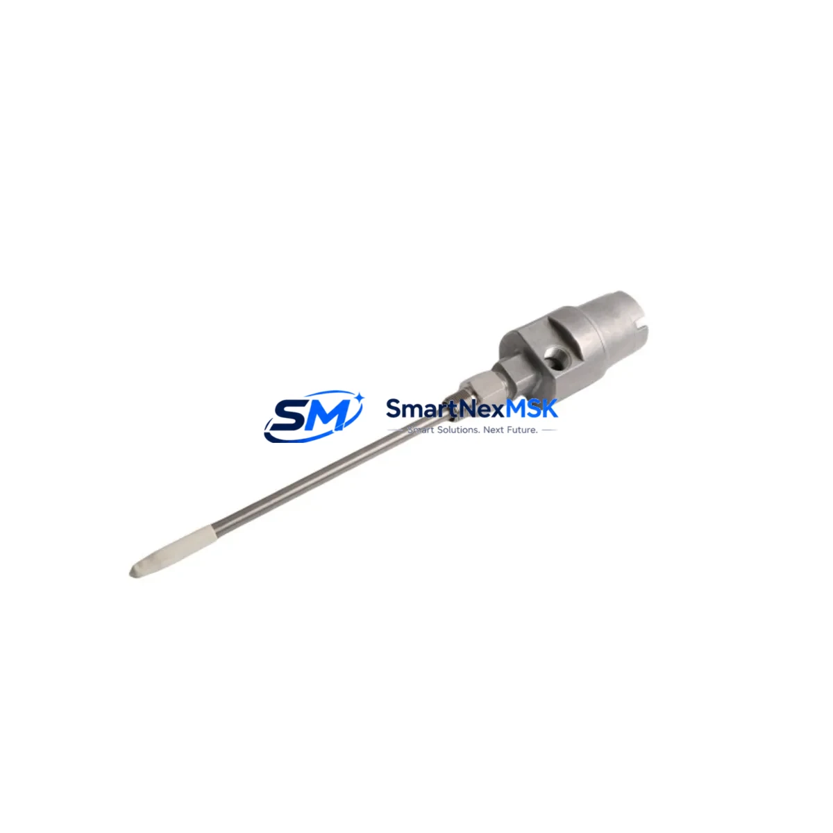
Bently Nevada 21000-16-05-00-078-04-02 Maintenance-Ready Spare for 21000 Series Automation
The Bently Nevada 21000-16-05-00-078-04-02 is an original proximity probe designed for the 21000 Series eddy-current transducer system — one of the most widely deployed vibration monitoring platforms in rotating machinery protection worldwide. Whether you are managing a planned turnaround, responding to an unplanned trip, or building a strategic spare parts inventory for a critical asset, this probe delivers the dimensional accuracy, gap voltage linearity, and signal integrity required for direct drop-in replacement without recalibration of the monitoring rack.
Maintenance engineers and reliability teams operating gas turbines, steam turbines, compressors, pumps, and gearboxes depend on the 21000 Series for continuous shaft displacement and vibration measurement. When a probe fails or reaches end-of-service life, every hour of unplanned downtime translates directly into production loss and safety risk. Stocking the 21000-16-05-00-078-04-02 as a certified spare eliminates the lead-time uncertainty that often extends outages by days or weeks when sourcing through OEM channels alone.
This unit ships fully tested, with output verified against Bently Nevada gap voltage specifications, and is backed by a 12-month warranty covering manufacturing defects and electrical performance. Each probe is individually inspected before dispatch to ensure the tip geometry, cable assembly, and connector termination meet the dimensional tolerances required for correct installation in the monitored machine train.
Spare Maintenance Table
| Parameter | Specification / Detail |
|---|---|
| Part Number / SKU | 21000-16-05-00-078-04-02 |
| Brand | Bently Nevada |
| Series | 21000 Series Eddy-Current Transducer System |
| Product Type | Proximity Probe (Non-Contact Displacement Transducer) |
| Sensing Technology | Eddy-Current (Inductive) |
| Probe Tip Diameter | 16 mm (per SKU designation) |
| Cable Length | 5 m (per SKU designation) |
| Extension Cable Compatibility | 3300 XL / 21000 Series extension cables |
| Driver / Oscillator Compatibility | Bently Nevada 21000 Series proximitor / driver modules |
| Output Signal | -18 VDC nominal at 1.0 mm gap (system-dependent) |
| Operating Temperature | -35°C to +177°C (probe body) |
| Target Material | Steel / Stainless Steel (ferromagnetic and non-ferromagnetic per calibration) |
| Application Environment | Rotating machinery: turbines, compressors, pumps, gearboxes |
| Installation | Direct drop-in replacement; no rack recalibration required |
| Origin | United States |
| Condition | Original / New |
| Pre-shipment Testing | Gap voltage output verified; dimensional inspection completed |
| Warranty | 12 Months — manufacturing defects and electrical performance |
| Shipping | Worldwide; expedited options available for emergency outage support |
Maintenance Planning for Continuous Operation
Replacing the 21000-16-05-00-078-04-02 proximity probe is rarely an isolated task. A thorough maintenance plan for the 21000 Series transducer loop requires the maintenance engineer to inspect and verify the condition of every component in the signal chain before returning the machine to service.
Begin with the 21000 Series extension cable that connects the probe to the proximitor driver. Extension cables are subject to mechanical fatigue, connector corrosion, and insulation degradation — particularly in high-temperature or high-vibration environments. A damaged extension cable will produce erratic gap voltage readings even with a new probe installed, leading to false alarms or missed trips. Inspect the full cable run and replace if continuity or insulation resistance is out of specification.
The Bently Nevada proximitor / driver module (such as the 21000 Series driver or compatible 3300 XL proximitor) should be bench-tested or substituted with a known-good spare during the probe replacement window. Driver module degradation is a common root cause of probe system failures that are misdiagnosed as probe faults. Verify the driver output voltage and sensitivity factor before closing out the work order.
At the monitoring rack level, inspect the 3500 Series or equivalent monitoring rack input card assigned to the affected channel. Check terminal block connections, verify channel configuration in the rack software, and confirm that the OK relay output is functioning correctly. Loose terminal connections on the rack input card are a frequent source of intermittent vibration alarms that are difficult to reproduce during static testing.
For the power supply feeding the monitoring system, verify that the 24 VDC or 28 VDC rack power supply module is within voltage tolerance and that redundant power supply modules are both healthy. A marginal power supply will cause system-wide instability that manifests as noise on all vibration channels simultaneously.
If the machine train includes a Keyphasor transducer (such as the Bently Nevada 3300 XL 8mm or 11mm Keyphasor probe), verify its gap and signal quality during the same maintenance window. The Keyphasor signal is used for phase reference across all vibration channels; a degraded Keyphasor will corrupt vector data for the entire machine train.
Where the vibration monitoring system interfaces with a DCS or safety system via 4–20 mA output cards or relay output modules, confirm that the analog output scaling and relay setpoints are correctly configured after any rack card replacement. Signal isolators or barriers in the loop should also be inspected for drift, particularly in installations where intrinsic safety barriers are used in hazardous area classifications.
Finally, review the condition of the probe mounting hardware and bracket assembly. Probe tip-to-shaft gap must be set within the linear range of the transducer system (typically 0.5 mm to 2.5 mm for 16 mm probes). Incorrect gap setting after installation is the single most common commissioning error and will result in immediate system faults or out-of-range alarms. Use a calibrated gap-setting tool and verify the DC gap voltage at the driver output before energizing the monitoring rack.
Site Replacement Workflow
Step 1 — Isolation and Permit: Obtain a valid work permit and isolate the monitoring channel at the rack. Do not de-energize the full monitoring rack if other channels are protecting running equipment. Use the channel inhibit function in the rack software to suppress alarms on the affected channel only.
Step 2 — Record As-Found Data: Before disconnecting the existing probe, record the as-found DC gap voltage at the driver output and note the physical gap measurement. This baseline is essential for comparing against the as-left condition after installation of the replacement probe.
Step 3 — Remove Existing Probe: Disconnect the extension cable at the probe connector. Remove the probe from the mounting bracket, noting the number of turns used to achieve the correct gap. Inspect the probe tip for physical damage, contamination, or corrosion that may indicate a root cause beyond normal wear.
Step 4 — Install Replacement Probe: Thread the 21000-16-05-00-078-04-02 replacement probe into the mounting bracket. Set the gap to the as-found measurement or the OEM-specified nominal gap, whichever is applicable. Reconnect the extension cable and verify connector seating.
Step 5 — Verify As-Left Condition: Measure the DC gap voltage at the driver output and confirm it falls within the linear range specified for the 21000 Series system. Compare against the as-found baseline. If the gap voltage is outside the expected range, re-check the physical gap and extension cable continuity before proceeding.
Step 6 — Release Channel and Confirm System Health: Remove the channel inhibit in the rack software. Confirm the OK relay is energized and that the vibration reading is stable and within normal operating range for the machine. Document the completed work order with as-found and as-left gap voltage values.
This workflow minimizes downtime, ensures system compatibility is maintained, and provides a documented audit trail for reliability and compliance records.
Spare Parts Support FAQ
Q: Is the 21000-16-05-00-078-04-02 a direct replacement for the original Bently Nevada part?
A: Yes. This is an original Bently Nevada 21000 Series proximity probe supplied as a maintenance spare. It is dimensionally and electrically equivalent to the factory-installed unit and requires no modification to the existing extension cable, driver module, or monitoring rack configuration for a standard replacement.
Q: What is the recommended spare parts inventory strategy for 21000 Series proximity probes?
A: For critical rotating machinery, reliability best practice recommends holding a minimum of one probe per monitored bearing position as an on-site spare, with additional spares for high-criticality assets such as main turbine shaft positions. Probes should be stored in their original packaging in a clean, dry environment away from strong magnetic fields. Shelf life for stored probes is typically five or more years when storage conditions are maintained.
Q: How is the probe tested before shipment?
A: Each 21000-16-05-00-078-04-02 unit undergoes pre-shipment electrical testing including gap voltage output verification at the nominal gap distance, continuity check of the cable assembly, and dimensional inspection of the probe tip and connector. A test report is available upon request for quality assurance documentation purposes.
Q: What does the 12-month warranty cover?
A: The 12-month warranty covers manufacturing defects and electrical performance failures under normal operating conditions. It does not cover damage resulting from incorrect installation, mechanical impact, chemical exposure, or operation outside the specified environmental limits. Warranty claims are supported by our technical team; contact [email protected] with the order reference and a description of the fault condition.
© 2026 SMARTNEXMSK. All rights reserved.
Original Source: https://smartnexmsk.com
Contact: [email protected] | +86 18259474341



