
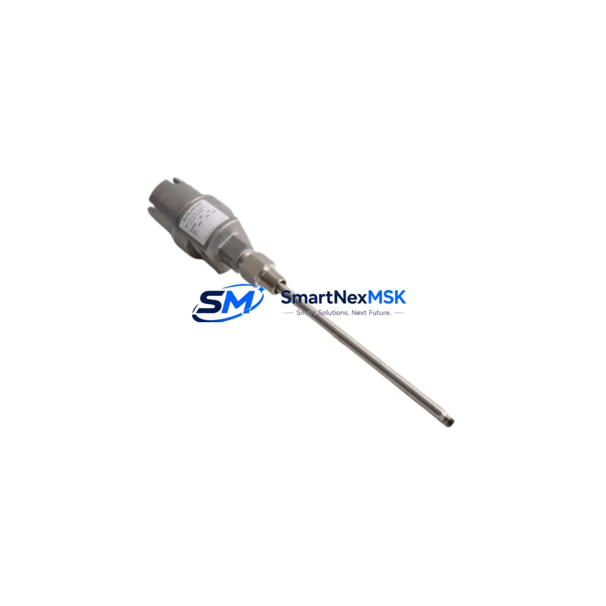
Bently Nevada 21000-16-05-15-084-03-02 Retrofit-Ready Proximity Transducer for 21000 Series Control Systems
The Bently Nevada 21000-16-05-15-084-03-02 is an eddy-current proximity transducer engineered for continuous vibration and position monitoring in rotating machinery protection systems. As legacy 21000 Series installations approach end-of-support cycles, this unit serves as a verified retrofit-ready replacement that preserves existing wiring infrastructure, signal conditioning architecture, and machinery protection logic without requiring a full system overhaul.
Industrial facilities operating Bently Nevada 3300 Series or 7200 Series monitoring systems frequently encounter the challenge of sourcing discontinued proximity transducer assemblies. The 21000-16-05-15-084-03-02 addresses this directly: its 8 mm tip diameter, 5-metre integral cable, and -24 VDC bias voltage output are dimensionally and electrically compatible with the original installation envelope, allowing maintenance teams to execute a like-for-like swap during a planned outage window rather than an emergency shutdown.
Upgrade Compatibility Table
| Parameter | 21000-16-05-15-084-03-02 | Retrofit Notes |
|---|---|---|
| Tip Diameter | 8 mm | Matches standard 21000 Series bore; no re-machining required |
| Cable Length | 5 m (integral) | Verify conduit run; extension cables available if needed |
| Bias Voltage Output | −24 VDC nominal | Compatible with 3300 XL 8mm driver/monitors |
| Sensitivity | 7.87 V/mm (200 mV/mil) | Confirm driver calibration range before commissioning |
| Temperature Range | −35 °C to +121 °C | Suitable for turbine bearing housings and compressor pedestals |
| Communication / Signal | Analogue (4–20 mA / voltage) | No protocol migration required; direct drop-in to existing I/O cards |
| Mounting Thread | M10 × 1 | Standard 21000 Series bracket; no adapter required |
| Warranty | 12 Months | Covered from date of shipment; includes pre-shipment functional test |
Retrofit Planning for Existing Automation Systems
A successful retrofit of the 21000-16-05-15-084-03-02 begins well before the maintenance window opens. Engineering teams should pull the existing loop drawing and confirm the driver module — typically a Bently Nevada 3300 XL 8mm Proximitor — is within its own calibration interval. If the Proximitor is also approaching end-of-life, replacing it alongside the transducer eliminates a second outage. The 3300 XL 8mm driver accepts the same connector pinout as the 21000 Series transducer, so terminal block re-wiring is not required.
For facilities running a Bently Nevada 3500 Series rack-based machinery protection system, the transducer feeds into a 3500/42M Proximitor I/O Module. Verify that the module’s gap voltage setpoints and alert/danger thresholds stored in the 3500 rack configuration software still reflect the new transducer’s sensitivity curve. If the rack communicates over Modbus RTU or Ethernet/IP to a DCS or SCADA layer — such as a Honeywell Experion PKS or an Emerson DeltaV system — no protocol migration is needed; the 3500 rack handles signal conversion transparently.
Where the legacy installation used a Bently Nevada 990 Direct Vibration Monitor or a standalone 1900/65 General Purpose Equipment Monitor, the 21000-16-05-15-084-03-02 can feed these monitors directly, provided the gap voltage is re-zeroed after installation. Document the as-found and as-left gap readings in the maintenance management system before closing the work order.
Facilities upgrading from older 7200 Series transducers to the 21000 platform should also audit the junction box terminal strips and cable glands. The 21000 Series integral cable uses a standard three-conductor shielded construction; confirm that existing conduit fill ratios accommodate the replacement cable diameter. If the control cabinet houses a Bently Nevada TK3 Transducer Calibration Kit, use it to verify the complete loop — transducer, extension cable, and driver — before returning the machine to service.
For multi-shaft train applications monitoring steam turbines, gas compressors, or large pumps, it is common to replace transducers in matched pairs (X–Y orientation) to maintain balanced sensitivity across both measurement planes. Coordinate with the vibration analyst to confirm that baseline spectrum data is captured immediately after commissioning so that any deviation from historical trends can be identified at the next scheduled data collection interval.
Downtime Control During System Migration
Minimising unplanned downtime during a proximity transducer replacement requires a structured pre-outage checklist. Before de-energising the loop, export the current 3500 rack configuration to a backup file using System 1 Evolution or the 3500 Rack Configuration Software — this preserves all setpoint, delay, and voting logic without manual re-entry. If the machine cannot be taken offline immediately, the 3500 rack’s bypass function allows the affected channel to be placed in bypass mode while the remainder of the protection system remains active, maintaining overall machinery protection continuity.
During the physical swap, use a calibrated gap-setting tool to position the transducer tip at the manufacturer-specified nominal gap (typically 1.0–1.5 mm for an 8 mm probe) before tightening the lock nut. Restore the channel from bypass, confirm the bias voltage reading at the monitor front panel, and verify that the OK relay is energised before releasing the machine to operations. The entire procedure — from bypass activation to channel restoration — can typically be completed within a two-hour planned maintenance window when spare parts are pre-staged and the configuration backup is available on-site.
All units supplied by SMARTNEXMSK undergo a pre-shipment functional test covering bias voltage, sensitivity linearity, and insulation resistance. A test certificate is included with each shipment, reducing the on-site commissioning burden and supporting your quality management system documentation requirements.
Retrofit Support FAQ
Q1: Is the 21000-16-05-15-084-03-02 a direct drop-in replacement for my existing 21000 Series transducer?
A: Yes. The unit shares the same M10 × 1 mounting thread, 8 mm tip diameter, integral 5 m cable, and −24 VDC bias output as the original 21000 Series specification. No mechanical modification or re-wiring is required in the majority of installations. Confirm the driver module model and gap voltage setpoint before commissioning.
Q2: What commissioning steps are required after installation?
A: Re-zero the gap voltage at the driver or monitor front panel, verify the OK relay status, confirm alert and danger setpoints against your machinery protection philosophy document, and capture a baseline vibration spectrum. If the transducer feeds a 3500 rack, restore the channel from bypass and confirm the rack’s system OK status before returning the machine to service.
Q3: Can this transducer be used with non-Bently Nevada monitoring systems?
A: The 21000-16-05-15-084-03-02 produces a standard analogue voltage output compatible with any eddy-current driver that accepts an 8 mm, 200 mV/mil sensitivity probe. It has been successfully integrated with third-party vibration monitors from SKF, Emerson, and Metrix, provided the driver’s input impedance and bias supply voltage are within specification.
Q4: What does the 12-month warranty cover, and what pre-shipment testing is performed?
A: Every unit is tested for bias voltage accuracy, sensitivity linearity, cable continuity, and insulation resistance prior to shipment. The 12-month warranty covers manufacturing defects and functional failure under normal operating conditions from the date of shipment. A test certificate is included with each unit to support incoming inspection and quality records.
© 2026 SMARTNEXMSK. All rights reserved.
Original Source: https://smartnexmsk.com
Contact: [email protected] | +86 18259474341



